
Transmittance spectrum measurement device and method for ultra-narrow band filter

An ultra-narrow-band filter and spectral measurement technology, which is applied in the field of transmittance spectral measurement devices, can solve problems such as low spectral resolution and poor wavelength accuracy, and achieve the effects of simple measurement methods, easy operation, and improved wavelength accuracy

Inactive Publication Date: 2014-12-03
SHANGHAI INST OF TECHNICAL PHYSICS - CHINESE ACAD OF SCI
View PDF1 Cites 8 Cited by
  • Summary
  • Abstract
  • Description
  • Claims
  • Application Information

AI Technical Summary

Problems solved by technology

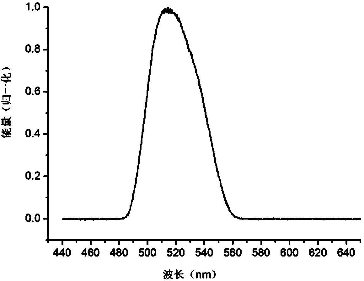
[0004] The present invention aims to overcome the shortcomings of poor wavelength accuracy and low spectral resolution when the traditional spectrophotometer measures the transmittance spectrum of the ultra-narrow-band filter, and provides an ultra-narrow-band filter transmittance with simple and practical structure and low cost. Measurement device and measurement method, and use the device to measure the transmittance spectrum of the ultra-narrow-band filter, so that the measurement results can more accurately characterize the spectral characteristics such as the central wavelength position and spectral bandwidth of the ultra-narrow-band filter

Method used


Image

  • Transmittance spectrum measurement device and method for ultra-narrow band filter
  • Transmittance spectrum measurement device and method for ultra-narrow band filter

Examples


Embodiment Construction

[0012] The present invention will be further described below in conjunction with the accompanying drawings.

[0013] Such as figure 1 As shown, the measuring device is mainly composed of a light source system 1, a converging mirror 2, a collimating mirror 3, a sample holder 4, an optical signal receiving system 5 and a data analysis and processing system 6, and the light source system, the converging mirror, the collimating mirror, The sample holder and optical signal receiving system constitute the entire optical path system of the measuring device. Place the optical system on a free optical table. In order to enable the measurement device to effectively collect the transmitted light signal of the ultra-narrow-band filter, adjust the positions of the light source system, converging mirror, collimating mirror, sample holder and optical signal receiving port so that they are on the same horizontal optical axis; adjust the converging mirror position, so that the transmitted li...


PUM


Abstract

The invention discloses a transmittance spectrum measurement device and method for an ultra-narrow band filter. The device comprises a light source system, a convergent mirror, a collimating mirror, a sample holder, a light signal receiving system, a data analyzing and processing system and the like. The device is characterized in that the light source system adopts an LED light source with stable high output power, continuous emission wavelength and emission spectrum bandwidth larger than 30 nm; a laser wavelength meter with high wavelength accuracy and high spectral resolution is used as a light signal receiver, a computer is used for data analyzing and processing, and finally a transmittance spectrum curve of the ultra-narrow band filter is obtained. According to the device, the structure is simple and practical, the constructing cost is low, the measurement method is simple, convenient, reliable and rapid, compared with a conventional spectrophotometer, both the wavelength accuracy and the spectral resolution of the device are higher, the actual spectrum performance of the ultra-narrow band filter can be accurately reflected, and the device and the method are particularly suitable for spectral bandwidth measurement and central wavelength locating of the ultra-narrow band filter with the bandwidth in the range of 0.1-1 nm.

Description

technical field [0001] The invention relates to a transmittance spectrum measuring device of an optical filter, in particular to a transmittance spectrum measuring device and a measuring method of an ultra-narrow-band optical filter. The spectral bandwidth and central wavelength of the filter. Background technique [0002] As an optical element for filtering and selecting spectral lines, narrowband filters are widely used in laser technology, biology, medical treatment, satellite remote sensing detection, optical communication and even quantum communication technology. In recent years, with the development of the above-mentioned technologies, the narrow-band filter is developing towards the demand of ultra-narrow band. The bandwidth of the common narrow-band filters is usually greater than 5nm, and the measurement of the transmittance spectrum can meet the measurement requirements with a traditional spectrophotometer. When the bandwidth of the ultra-narrow-band filter is l...

Claims


Application Information

Patent Timeline
IPC IPC(8): G01J3/28
Inventor 马小凤刘定权王曙光蔡清元陈刚张莉朱佳琳
Owner SHANGHAI INST OF TECHNICAL PHYSICS - CHINESE ACAD OF SCI
Learn More