Safe and intelligent fault indicator for overhead line

A technology for fault indicators and overhead lines, which is applied to fault locations, instruments, and measuring devices. It can solve the problems of reducing the working efficiency of the magnetic circuit system of transformers, expensive equipment for ring winding machines, and damage to fault indicators. The internal water leakage structure realizes the effect of remote detection management and avoids damage

Active Publication Date: 2014-12-03
HAIYAN LINGYUNWEI ELECTRONICS +2
View PDF10 Cites 11 Cited by
  • Summary
  • Abstract
  • Description
  • Claims
  • Application Information

AI Technical Summary

Problems solved by technology

[0005] 2. The C-type transformer coil needs to be installed on the ring winding machine synchronously with the iron core when winding, and it needs to be wound back and forth during winding. The work efficiency is very low, and the ring winding machine is expensive and not suitable for mass production.
[0006] 3. The iron core of the C-type transformer adopts a cross-section with an area ratio of 1:1. Due to the small contact surface and large magnetic loss, the working efficiency of the entire transformer magnetic circuit system is reduced and the accuracy is affected.
[0007] 4. The entire fault indicator of the C-type transformer is suspended on the overhead line all the year round, and the design of some fault devices also exposes the iron core directly after painting, which will be challenged by various natural conditions. In terms of waterproofing, because Defects in the existing fault indicator design often lead to damage to the fault indicator due to water seepage, and changes in thermal expansion and contraction will cause a gap between the two iron cores, affecting accuracy

Method used


Image

  • Safe and intelligent fault indicator for overhead line
  • Safe and intelligent fault indicator for overhead line
  • Safe and intelligent fault indicator for overhead line

Examples


Embodiment Construction

[0036] In order to more clearly illustrate the technical problems, technical solutions and beneficial effects to be solved by the patent of the present invention, the present invention will be further described in detail below in conjunction with the accompanying drawings and embodiments.

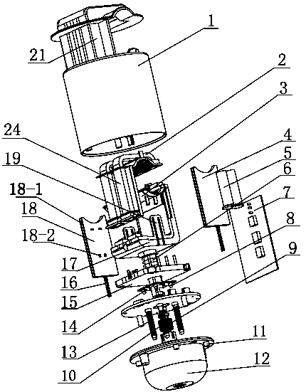
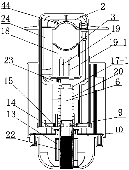
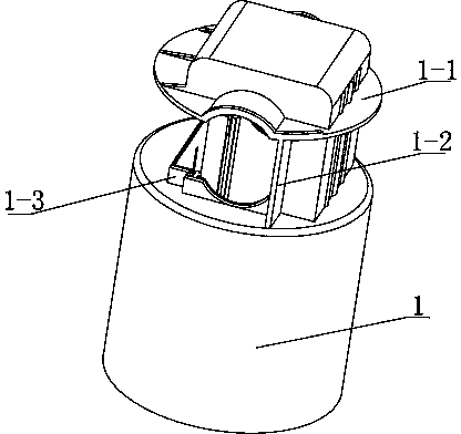
[0037]As shown in the figure, the main housing 1 of the overhead line safety intelligent fault indicator of the present invention is provided with a transformer, the lower end of the transformer is connected to a direct-push locking device, and the lower part of the direct-push locking device is provided with a dismounting device for suspension , the main housing is provided with two independent cavities, respectively the inner cavity 26 and the outer cavity 25, the upper end of the main housing is provided with a hook 21 connected with the main housing, adopting the design of the inner cavity and the outer cavity, the failure The circuit part of the indicator is separated from the locking p...


PUM


Abstract

The invention relates to a safe and intelligent fault indicator for an overhead line. A main housing is internally provided with a mutual inductor, a direct-pushing-type locking device and a circuit system. The lower end of the main housing is provided with a transparent lampshade cooperated with the main housing. The mutual inductor comprises two groups of iron cores in parallel arrangement, wherein the two groups of iron cores are respectively cut into two portions, the inclined plane angle forming a 45-degree angle with the cross section of the iron core, so that the problems of low work efficiency, expensive equipment and being incapable of volume produce since an original C-type mutual inductor coil winding needs to be installed to an annular winding machine with the iron cores synchronously; through adopting a U-shaped iron core structure of the diagonal plane, magnetic loss is reduced; and the intelligent fault indicator can enable fault or short circuit information of the overhead line and load terminal equipment to be selectively encrypted through a security chip ESAM and the encrypted is then sent to an electric management master station and mobile phones of operation and maintenance personnel, thereby realizing remote detection management, fault location and high-efficiency processing, and providing powerful guarantee for an electric system.

Description

technical field [0001] The invention relates to a fault detection and alarm device for power systems, in particular to an overhead line safety intelligent fault indicator. Background technique [0002] The overhead line fault indicator can detect the running status of the line in real time through the main station, detect and collect various load data to solve the problem of line and line load equipment. After the original line maintenance personnel can only visually inspect each section, line, and pole The original operation of line checking solves the problems of high work intensity of the original line maintenance personnel, long time for troubleshooting, and the safety risks of climbing mountains and wading in some places, and provides a powerful solution for fast fault location and troubleshooting of the distribution network. Assure. [0003] But the existing fault indicators have the following problems. [0004] 1. The opening transformer used in the fault indicator ...

Claims


Application Information

Patent Timeline
Patent Type & Authority Applications(China)
IPC IPC(8): G01R31/08G01R31/02
Inventor 钱金华汤林斌张劲超顾翔张宇徐光年朱升涛沈春林黄竹志
Owner HAIYAN LINGYUNWEI ELECTRONICS
Why Eureka
Try Eureka