Multimodal microscopic imaging system

A microscopic imaging, multi-modal technology, applied in medical science, sensor, endoscope, etc., can solve the problems of difficult coaxial, limited scanning speed, limited matching accuracy of scanning area, etc., to achieve simplified system structure, The effect of increased stability

Active Publication Date: 2014-12-10
SHANGHAI JIAO TONG UNIV
View PDF7 Cites 29 Cited by
  • Summary
  • Abstract
  • Description
  • Claims
  • Application Information

AI Technical Summary

Problems solved by technology

However, the optical system of this technology uses a dual light source system. When adjusting the optical path, it is difficult to ensure that the two beams of light are completely coaxial when passing through the dichroic mirror through the adjustment of the optical device, and at the same time increase the cost of the system and the cost of the system. Complexity; and the scanning method is mechanical moveme

Method used


Image

  • Multimodal microscopic imaging system
  • Multimodal microscopic imaging system
  • Multimodal microscopic imaging system

Examples


Embodiment 1

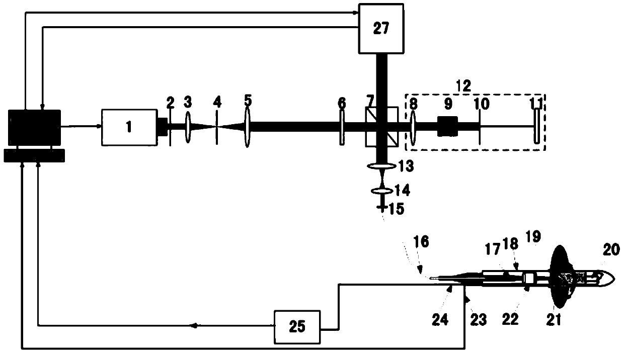
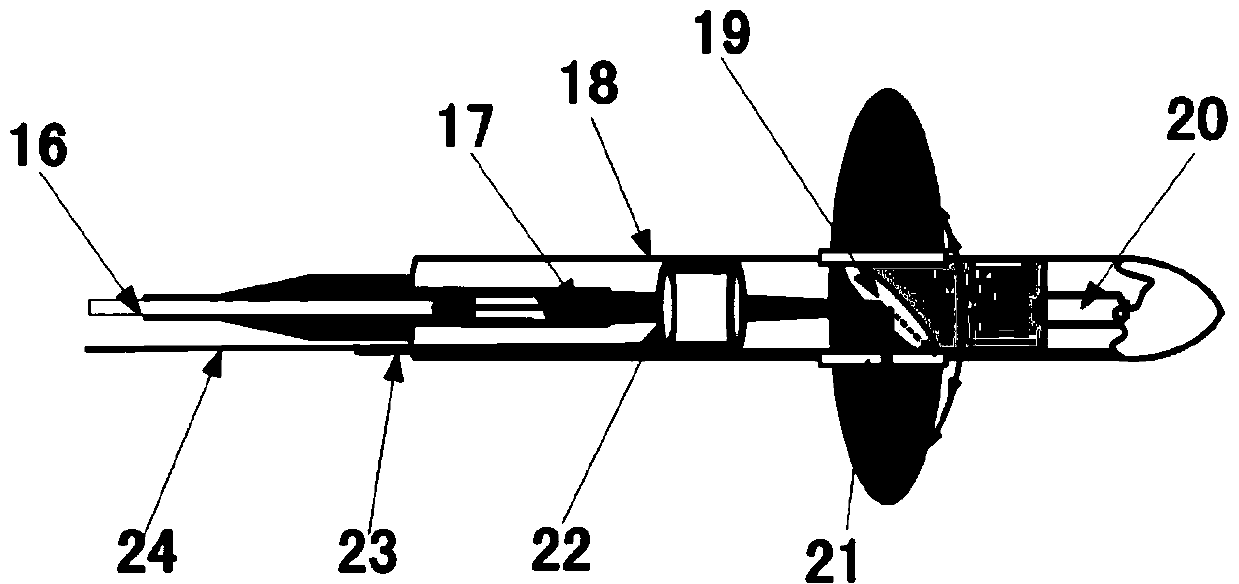
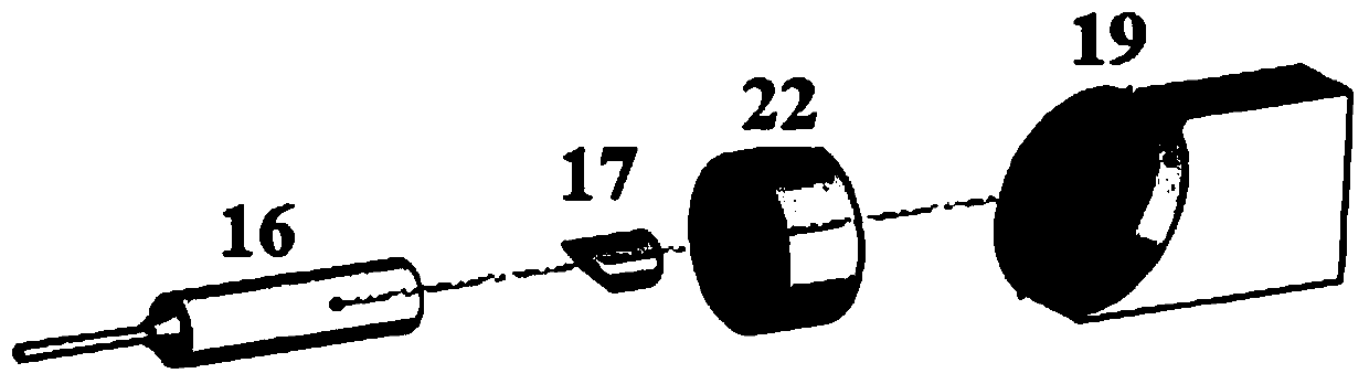
[0023] Such as figure 1 , figure 2 and image 3 As shown, this embodiment includes: laser light source 1, variable diaphragm 2, first lens group 3, 5, pinhole diaphragm 4, optical filter 6, beam splitter 7, reference arm 12, second lens group 13 , 14, collimating coupler 15, single-mode optical fiber 16, focusing lens 17, stainless steel sleeve 18, scanning mirror 19, driving motor 20, scanning window 21, ultrasonic transducer 22, motor cable 23, connecting wire 24, amplifier 25, control computer 26, photoelectric detector 27.

[0024] The reference arm 12 includes a focusing lens 8 , a dispersion compensation block 9 , a tunable diaphragm 10 and a mirror 11 .

[0025] The focusing lens 17 has the characteristic of gradually decreasing gradient refractive index distribution, which enables the light beam to transmit along the central axis of the endoscopic probe to produce continuous refraction, so that the incident beam converges smoothly and continuously, and focuses on o...

Embodiment 2

[0031] Such as figure 1 , figure 2 and image 3 As shown, this embodiment includes: an optical coherence tomography subsystem, a photoacoustic microscopic imaging subsystem, and an ultrasonic imaging subsystem combined with a multi-modal endoscopic imaging system composed of an endoscopic probe, and its main implementation steps as follows:

[0032] The first step: the laser light source 1 generates laser light and adjusts the spot size through the variable aperture 2, then passes through the first lens group 3, 5 and the pinhole aperture 4, the beam is collimated and expanded, and then enters the optical filter 6 for filtering. The light then passes through the beam splitter 7, a part of the laser light passes through the focusing objective lens 8, passes through the dispersing block 9, and passes through the adjustable aperture slit 10 to the mirror 11. This part serves as the reference arm 12 for optical coherence tomography, and the other part passes through the second ...


PUM

PropertyMeasurementUnit
Diameteraaaaaaaaaa
Diameteraaaaaaaaaa
Lengthaaaaaaaaaa

Abstract

A multimodal microscopic imaging system performs detection by an optical means. Lasers generated by a laser source enter a light filter through a light beam collimation and beam expanding mechanism to be filtered, then, part of the lasers enter a reference arm to generate weak coherent signals through a spectroscope, the other part of the lasers sequentially pass through a collimation coupling mechanism and a light beam guiding and focusing mechanism to form focused light beams, the focused light beams enter an electric scanning device arranged on a detection window through an ultrasonic transducer, biological tissue to be detected is subjected to circular scanning through the electric scanning device, and the focused light beams induce the biological tissue to generate back scattering photons and opto-acoustic signals on the biological tissue to be detected. The internal structure and the functions of the biological tissue are imaged, and fast multimodal two-dimensional and three-dimensional images are provided for accurately monitoring the internal structure and function changes of the biological tissue.

Description

technical field [0001] The invention relates to a detection system using optical means, in particular to a multi-mode microscopic imaging system. Background technique [0002] Ultrasonic endoscopic imaging (USE) is the most commonly used imaging technology in the field of clinical biomedicine. It is mainly based on the detection of the mechanical properties of biological tissues and the differences in mechanical properties of biological tissues. interface imaging. Optical coherence tomography (OCT) mainly uses the weakly coherent interference signals of tissue scattered photons to detect the changes in the back reflection or scattering intensity of incident photons by tissues at different depths inside biological tissues, so as to obtain biological data within a certain depth range. Tissue microstructure information, and then obtain two-dimensional or three-dimensional structure imaging of biological tissue through transverse scanning. Photoacoustic microscopic imaging tec...

Claims


Application Information

Patent Timeline
IPC IPC(8): A61B5/00A61B1/05
Inventor 周传清柴新禹赵庆亮
Owner SHANGHAI JIAO TONG UNIV
Why Eureka
Try Eureka