Steel ball surface defect detection sorting equipment

A defect detection and steel ball technology, applied in sorting, optical testing defects/defects, chemical instruments and methods, etc., can solve the problems of false detection, high false detection rate and low efficiency of steel ball sorting equipment, to avoid The effect of missed detection and reduction of false detection rate

Active Publication Date: 2014-12-10
NINGBO BAIJIABAI MEASUREMENT & CONTROL EQUIP
View PDF17 Cites 19 Cited by
  • Summary
  • Abstract
  • Description
  • Claims
  • Application Information

AI Technical Summary

Problems solved by technology

Wang Peng, Wu Chunya and others from the School of Mechanical Power Engineering of Harbin University of Science and Technology proposed a steel ball surface defect detection method using LabView as the software platform combined with the IMAQ Vision function library. The characteristics of the damaged texture of the defect area can complete the judgment of the existence and type of defects on the surface of the steel ball. The size of the defect cannot be accurately calculated, and the image of the entire outer surface of the steel ball cannot be captured.
Dr. Pan Hongping from Harbin Institute of Technology also proposed an experimental device for automatic detection, recognition and classification of steel ball surfaces using cameras and computer image processing and recognition technology. The steel ball rolls on the self-made stage in order to capture the images of the steel ball in all directions, and realizes the automatic detection of the surface defects of the steel ball, but there is no guarantee that the steel ball is fully unfolded on the self-made stage, and it cannot be guaranteed that it can be captured Image to each preset point
Song Xiaoxia of Henan University of Science and Technology proposed an experimental platform for steel ball surface unfolding. According to the testing requirements, two mutually perpendicular tracks were designed. The steel ball rolls on the two vertical tracks by its own gravity in order to capture the entire steel ball. However, due to the two-dimensional mechanical movement of the steel ball, it is random and complicated to obtain the full coverage image of the steel ball surface
Chinese patent (notification number CN102658266B) discloses a steel ball sorting device and method based on machine vision, which uses the detection cavity in the feed plate to carry steel balls to rotate at a certain speed, and the expansion of the steel balls depends on the period of the bottom friction plate The rotation and intermittent translation make the steel ball move eccentrically, so as to achieve the effect of spreading the surface of the steel ball to be detected. However, the image obtained by this method is random, and it cannot guarantee complete coverage of the steel ball surface, and the mechanism is also relatively complicated.
Chinese patent (Notice No. CN102288620B) discloses a method and device for unfolding the surface of a steel ball based on a multi-image sensor. The device uses the self-gravity of the steel ball to roll on a one-dimensional track. The surface of the steel ball is fully covered, so the structure of its unfolding mechanism is very simplified, but in the actual use of the device (see patent announcement No. figure 1 ), the steel balls on the one-dimensional track are arranged continuously, and the two adjacent steel balls are in close contact. If the contact surface of two adjacent steel balls has defects such as pits or rust spots, it will Affect its relative rolling, so that the steel ball slides along the one-dimensional track, and cannot fully roll and unfold, resulting in the inability to capture a complete steel ball surface image and resulting in missed detection. The false detection rate is as high as 3-5‰, which is obviously not applicable Because of the industrial batch sorting of steel balls, it is necessary to improve it
Also refer to a steel ball surface defect detection automatic sorting device disclosed in Chinese patent (notification number CN102680490A). The existing steel ball sorting equipment or devices do not fully consider the actual situation of steel ball processing, resulting in The function of the equipment is single, only to detect and automatically sort the surface defects of steel balls under ideal conditions
However, in the actual steel ball processing industry, after the steel ball is processed from the grinding machine, the steel ball cannot be in contact with the air for a long time, and needs to be placed in kerosene to avoid oxidation and rust. Therefore, the steel ball sorting equipment needs to place the steel ball in kerosene Image capture and sorting are carried out in the center; after the steel balls are processed and formed by the grinding machine, the surface of the steel balls still has oil stains, which will cause false detections by the steel ball sorting equipment, resulting in a high false detection rate, so when the steel balls enter the sorting equipment The surface of the steel ball needs to be cleaned before testing. The existing steel ball sorting equipment does not have the function of cleaning the surface of the steel ball. At present, the surface of the steel ball is cleaned manually, which is inefficient and is easy to damage the surface of the steel ball during cleaning. ; In addition, the existing steel ball surface defect detection and sorting equipment does not have the function of sorting the size of the steel balls, and the steel balls can be dip-coated with anti-rust oil after being sorted by at least two devices; When the steel balls are taken out from the kerosene after sorting, some kerosene remains on the surface of the steel balls, which will affect the anti-rust oil dipping on the surface of the steel balls, resulting in poor anti-rust effect on the surface of the steel balls

Method used


Image

  • Steel ball surface defect detection sorting equipment
  • Steel ball surface defect detection sorting equipment
  • Steel ball surface defect detection sorting equipment

Examples


Embodiment 1

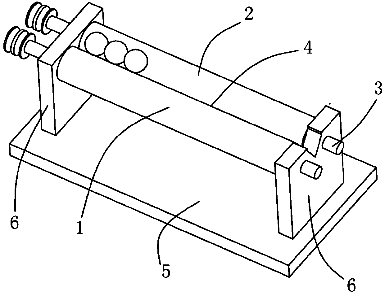
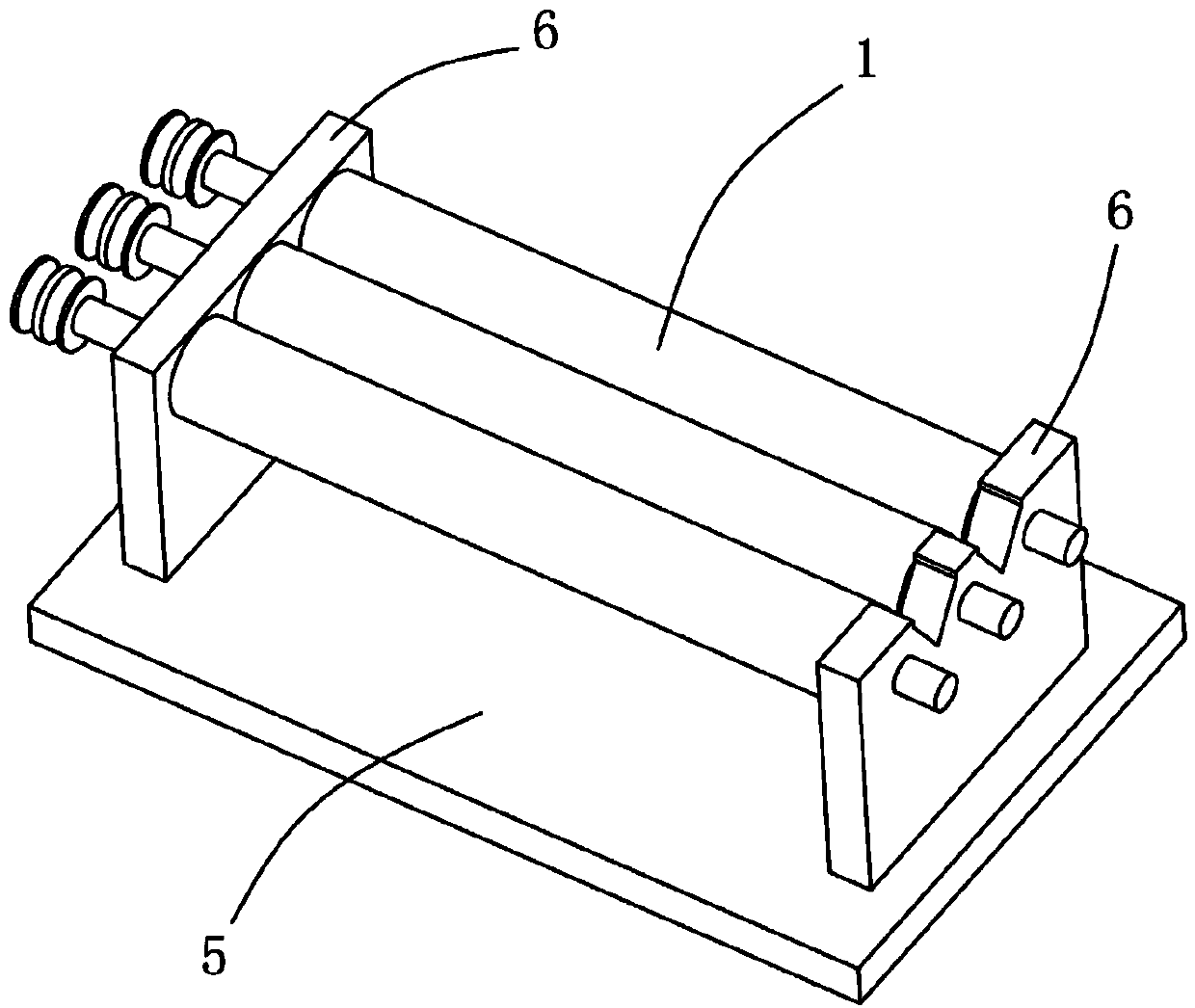
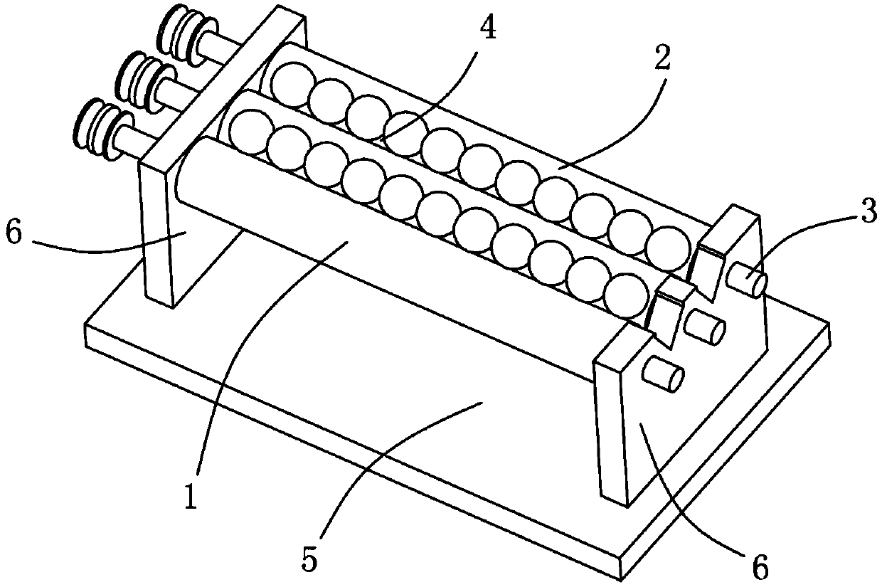
[0038] A steel ball surface defect detection and sorting device includes a steel ball size screening device, a steel ball surface unfolding device, a camera, a sorting device and a control module, and the camera and the sorting device are respectively connected to the control module. The steel ball entry end of the storage tank 4 of the steel ball surface unfolding device is connected with the qualified steel ball discharge end of the steel ball size screening device through the feeding channel, and the qualified steel balls screened by the steel ball size screening device are fed from the feeder. The channels enter the steel ball surface unfolding device one by one, the camera is arranged above the accommodating groove 4 of the steel ball surface developing device, and the sorting device is arranged at the steel ball roll-out end of the steel ball surface developing device's accommodating groove 4. The steel balls first pass through the steel ball size screening device to sele...

Embodiment 2

[0060] A steel ball surface defect detection and sorting device includes a steel ball surface cleaning device, a steel ball surface unfolding device, a camera, a sorting device and a control module, and the camera and the sorting device are respectively connected to the control module. The steel ball entry end of the storage tank 4 of the steel ball surface unfolding device is connected with the steel ball discharge end of the steel ball surface cleaning device through the feeding channel, and the steel balls cleaned by the steel ball surface cleaning device enter from the feeding channel one by one. The steel ball surface unfolding device, the camera is arranged above the accommodation groove 4 of the steel ball surface unfolding device, and the sorting device is arranged at the steel ball roll-out end of the steel ball surface unfolding device's accommodation groove 4. The steel ball first passes through the steel ball surface cleaning device for surface cleaning, and then th...

Embodiment 3

[0065] A steel ball surface defect detection and sorting device includes a steel ball size screening device, a steel ball surface cleaning device, a steel ball surface unfolding device, a camera, a sorting device and a control module, and the camera and the sorting device are respectively connected to the control module. The steel ball entering end of the spiral groove 18 of the steel ball surface cleaning device communicates with the second gap section L2 of the steel ball size screening device through the feeding channel, and the steel ball rolling end of the steel ball surface cleaning device spiral groove 18 is connected with the steel ball The accommodating tanks 4 of the spherical surface spreading device communicate with each other through feeding channels. The camera is arranged above the accommodating groove 4 of the steel ball surface developing device, and the sorting device is arranged at the steel ball rolling end of the accommodating groove 4 of the steel ball sur...


PUM


Abstract

The invention discloses steel ball surface defect detection sorting equipment. The steel ball surface defect detection sorting equipment comprises a steel ball size screening device, a steel ball surface cleaning device, a steel ball surface unfolding device, a camera, a sorting device and a control module, wherein the steel ball size screening device comprises two parallel rolling shafts; the steel ball surface cleaning device comprises a trapezoid rotary table and a rotary sleeve covering the rotary table; the steel ball surface unfolding device comprises at least two rolling bars, wherein a containing groove is formed between two adjacent rolling bars, and at least one rotatable rolling bar in the two adjacent rolling bars can be used for driving steel balls to roll in the containing groove in synchronism with the rolling bars. The equipment disclosed by the invention can screen out the out-of-size steel balls and can clean the surfaces of the steel balls so as to prevent the false detection caused by blots on the surfaces of the steel balls; in combination with the specific steel ball surface unfolding device, the steel ball surface defect detection storing equipment can rapidly and accurately sort the steel ball sizes and the steel ball surface defects, and the steel ball sorting efficiency is greatly promoted.

Description

technical field [0001] The invention relates to the technical field of steel ball sorting equipment based on machine vision, in particular to a steel ball surface defect detection and sorting equipment. Background technique [0002] Machine vision is to use machines instead of human eyes for measurement and judgment. Machine vision technology refers to converting the captured target into an image signal through machine vision products (ie, image capture device, which is divided into CMOS and CCD) and transmitting it to a dedicated image. The processing system converts the information into digital signals according to pixel distribution, brightness, color and other information; the image system performs various calculations on these signals to extract the characteristics of the target, and then controls the on-site equipment actions according to the results of the discrimination. [0003] The surface defect detection of bearing steel balls based on machine vision technology i...

Claims


Application Information

Patent Timeline
Patent Type & Authority Applications(China)
IPC IPC(8): B07C5/06B07C5/34G01N21/89B08B1/02
Inventor 李方
Owner NINGBO BAIJIABAI MEASUREMENT & CONTROL EQUIP
Why Eureka
Try Eureka