
Device used for rolling battery pole piece at high speed

A battery pole piece, high-speed technology, applied in the direction of metal rolling, electrode manufacturing, etc., can solve the problems of battery pole piece rolling thickness, reduce production efficiency, increase production cost, etc., to save the time of changing rolls and splicing, The effect of reducing the time for changing rolls and improving production efficiency

Active Publication Date: 2014-12-10
邢台纳科诺尔精轧科技股份有限公司
View PDF10 Cites 15 Cited by
  • Summary
  • Abstract
  • Description
  • Claims
  • Application Information

AI Technical Summary

Problems solved by technology

[0003] Lithium battery pole piece rolling mill, referred to as rolling mill, is one of the main equipment of the battery pole piece production line. Increasing the rolling speed of the rolling mill can improve production efficiency, but it also puts forward higher requirements for the rolling mill itself. Currently, the rolling speed of rolling mills on the market is The maximum speed is about 30m / min, and the speed of a few foreign manufacturers can reach up to 60m / min. When the speed of the rolling mill is too fast, the rolling thickness of the battery pole piece is affected, and the accuracy is difficult to guarantee
During the rolling process, when it comes to replacing the battery pole piece coil, the production line needs to be shut down and restarted after the coil change and splicing are completed. This production method reduces production efficiency, and the high-speed production line frequently stops in an emergency , Stopping, and starting are also likely to cause adverse effects on the machine, shortening the service life and increasing production costs

Method used


Image

  • Device used for rolling battery pole piece at high speed
  • Device used for rolling battery pole piece at high speed
  • Device used for rolling battery pole piece at high speed

Examples


Embodiment Construction

[0031] The present invention will be further described in detail below in conjunction with the drawings and specific embodiments:

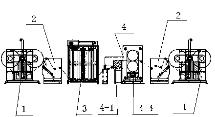
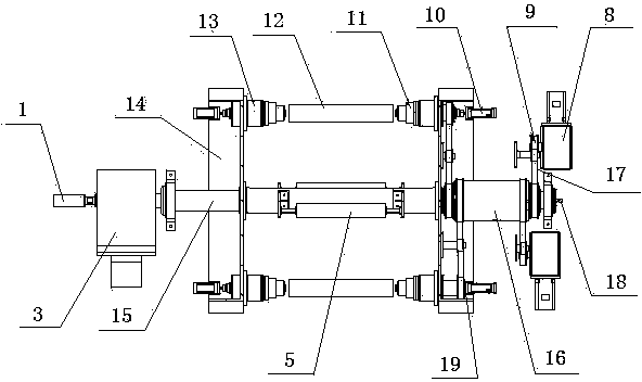
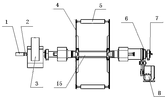
[0032] Such as figure 1 As shown, the device for high-speed rolling of battery pole pieces includes a control system, a dual-station automatic rewinding and unwinding machine 1, a belt connecting device 2, a sheet storage mechanism 3, and a rolling mechanism 4. Two sets of winding machine 1 are installed at the initial end and the end, respectively. The splicing device 2 is placed on the side of the output end of the battery pole piece coil of the dual-station automatic winding and unwinding machine 1 at the initial end, and the output end of the splicing device 2. After that, the sheet accumulation mechanism 3 and the roll pressing mechanism 4 are arranged in sequence. The output end of the roll pressing mechanism 4 is connected with the double-station automatic winding and unwinding machine 1 at the end. The automatic winding and connecting mechanis...


PUM


Abstract

The invention discloses a device used for rolling a battery pole piece at a high speed. The device comprises a control system, two double-station automatic winding and unwinding machines, a band connecting device, a piece storage mechanism and a rolling mechanism. The double-station automatic winding and unwinding machines are arranged at an initial end and a tail end respectively. The band connecting device is arranged on the side face of the output end of a battery pole piece band roll of the double-station automatic winding and unwinding machine arranged at the initial end. The piece storage mechanism and the rolling mechanism are sequentially arranged behind the output end of the band connecting device. The output end of the rolling mechanism is connected with the double-station automatic winding and unwinding machine arranged at the tail end. An automatic roll replacing and band connecting mechanism, the piece storage mechanism and the rolling mechanism are all connected with a control system. According to the device, rolling accuracy can be guaranteed, shutdown is not required in the rolling process, roll replacement and band connection are automatically completed, and therefore automated production is achieved.

Description

Technical field [0001] The invention relates to a rolling machine, in particular to a machine for rolling and producing battery pole pieces. Background technique [0002] The lithium battery is composed of a battery cell, an electrolyte, a protection circuit, and a casing. The battery cell includes a positive electrode, a negative electrode and a diaphragm. Both the positive and negative electrodes are called battery pole pieces. In order to improve the consistency of the density and thickness of the battery pole pieces, the positive and negative pole pieces must be rolled after the coating process. This process is called battery pole piece rolling. The process of battery pole piece rolling is a process in which the battery pole piece is drawn between the rotating rolls by the friction generated between the roller and the battery pole piece, and the battery pole piece is deformed under pressure. [0003] The lithium battery pole piece rolling mill is referred to as the rolling mil...

Claims


Application Information

Patent Timeline
IPC IPC(8): B21B1/22B21C47/02B21C47/16B21C47/26B21C47/34H01M4/04
CPCY02E60/10
Inventor 王海斌付建新耿建华
Owner 邢台纳科诺尔精轧科技股份有限公司
Learn More