Preparing method for porous metal matrix compound brazing filler metal alloy soldering head

A technology of porous metal and composite solder, which is applied in welding equipment, metal processing equipment, manufacturing tools, etc. It can solve the problem that the joint welding rate is difficult to be guaranteed, the overall mechanical properties of the joint are poor, and the molten solder alloy is difficult to wet Spreading and other issues to achieve the effect of improving the bonding strength

Active Publication Date: 2014-12-10
CHINA NAT ELECTRIC APP RES INST +1
View PDF7 Cites 24 Cited by
  • Summary
  • Abstract
  • Description
  • Claims
  • Application Information

AI Technical Summary

Problems solved by technology

It is conceivable that in the traditional brazing process (non-ultrasonic assisted brazing), if this porous matrix composite solder alloy is used for brazing, it is difficult for the molten solder alloy to achieve sufficient wetting and spreading on the surface of the base metal
Although the strength of the brazing seam layer of the joint can be improved, the welding rate of the joint is difficult to be guaranteed, and the overall mechanical properties of the joint are still poor

Method used


Image

  • Preparing method for porous metal matrix compound brazing filler metal alloy soldering head
  • Preparing method for porous metal matrix compound brazing filler metal alloy soldering head
  • Preparing method for porous metal matrix compound brazing filler metal alloy soldering head

Examples


Embodiment 1

[0039] see figure 1 , take a piece of porous Ni foil with a thickness of 250 μm and a size of 20 mm × 20 mm, place the porous Ni foil in absolute ethanol for ultrasonic cleaning, and then immerse the Ni foil in molten pure Sn and shake it several times after air-drying. Take out the porous Ni foil, and now pure Sn has been impregnated in the porous Ni metal foil, and a porous Ni-based composite solder sheet filled with pure Sn has been formed;

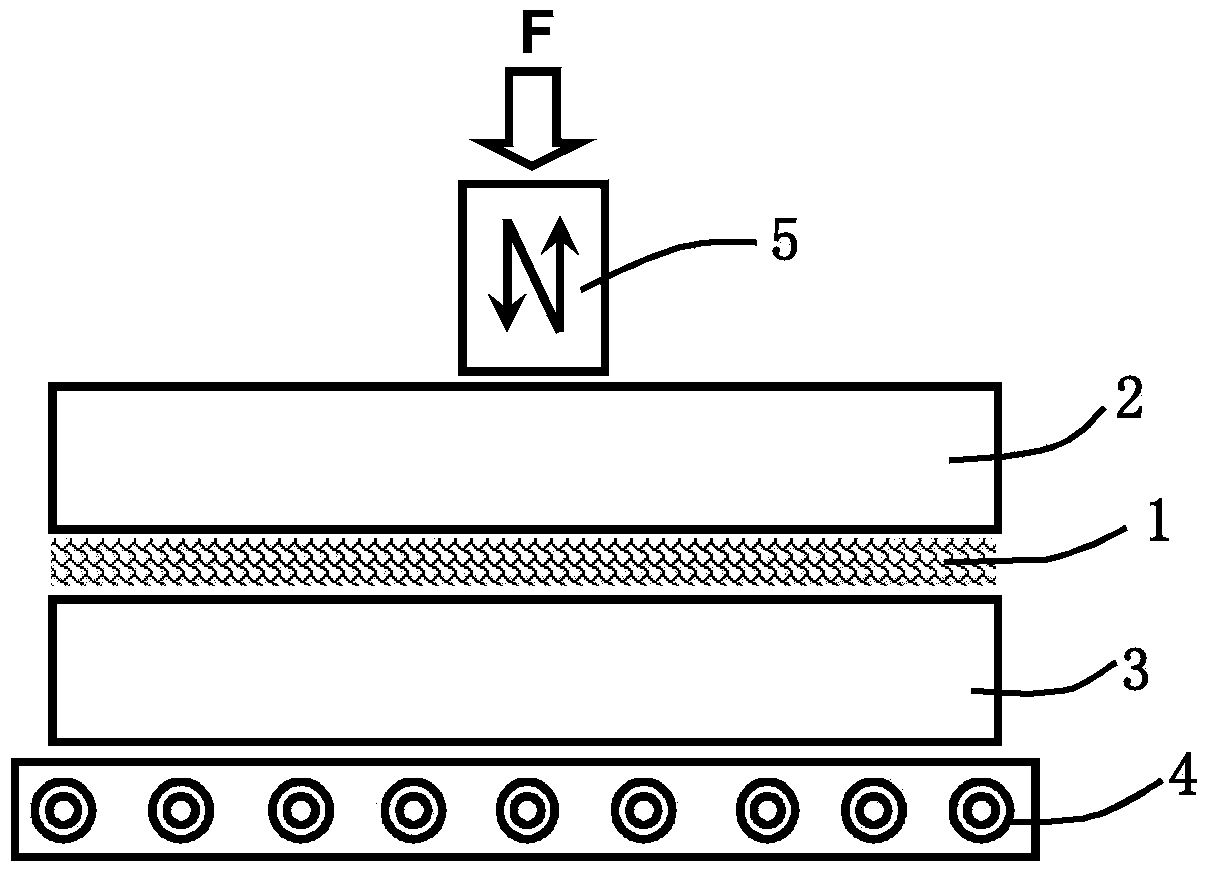
[0040] see figure 2 , take two pieces of 1060-Al alloy with a size of 20mm×20mm×3mm, place the composite solder piece 1 between the upper Al base material 2 and the lower Al base material 3, and place the assembled joint with a restraint Fixture on hot plate 4. Apply the tool head 5 of the ultrasonic vibration device to the surface of the upper Al base material 2 and apply a pressure of 1 MPa, then turn on the heating device to heat the joint, and when the solder alloy starts to melt and overflow, turn on the ultrasonic vibration. T...

Embodiment 2

[0043] see figure 1 , take a piece of porous Ni foil with a thickness of 100 μm and a size of 10 mm × 10 mm, place the porous Ni foil in absolute ethanol for ultrasonic cleaning, air-dry and then immerse the Ni foil in molten pure Sn and shake it several times, then Take out the porous Ni foil, at this time pure Sn has been impregnated in the porous Ni metal foil, and a porous Ni-based composite solder sheet filled with pure Sn has been formed, and finally, the composite solder sheet is cut into a diameter of round brazing sheet.

[0044] see Figure 4, take the diameter as Two T2-Cu metal rods with a length of 40mm are assembled with the Cu rod and the composite solder alloy sheet 1, wherein the lower Cu rod 32 is fixed by the clamp, and the upper Cu rod 22 has a degree of freedom along the direction of the Cu rod axis, The composite solder alloy sheet 1 is placed between two Cu rods, the tool head 5 of the ultrasonic vibration device is applied to the end of the upper C...

Embodiment 3

[0047] see figure 1 , take a piece of porous Ni foil with a thickness of 200 μm and a size of 10 mm × 10 mm, place the porous Ni foil in absolute ethanol for ultrasonic cleaning, air-dry and then immerse the Ni foil in molten pure Sn and shake it several times, then The porous Ni foil is taken out, and the pure Sn has been infiltrated into the porous Ni metal foil at this time, and a porous Ni-based composite solder sheet filled with pure Sn is formed.

[0048] see Image 6 , take a piece of 1060-Al alloy and a T2-Cu alloy with a size of 10mm×10mm×3mm, place the composite solder sheet 1 between the Al base material 23 and the Cu base material 33, and place the assembled joint On the electric heating plate 4 with a limiting fixture, in which the Al base material 23 is on the top and the Cu base material 33 is on the bottom, the tool head 5 of the ultrasonic vibration device is applied to the upper surface of the Al base material 23 and a pressure of 2 MPa is applied, and then ...


PUM

PropertyMeasurementUnit
thicknessaaaaaaaaaa
melting pointaaaaaaaaaa
thicknessaaaaaaaaaa

Abstract

The invention discloses a preparing method for a porous metal matrix compound brazing filler metal alloy soldering head. The method adopts porous metal matrix compound brazing filler metal alloy filled up with brazing filler metal alloy, a compound brazing filler metal layer is prefabricated between hard base metal, then the brazing filler metal alloy filled into the porous metal layer is heated to melt, and a tool head of an ultrasonic vibrating device acts on the surface of the base metal and exerts certain-pressure certain-time ultrasonic vibration on the surface of the base metal to finish a brazing process. When the method is used for preparing the brazing soldering head, the porous metal with high melting point can have a supporting function to a soldering seam layer in a brazing soldering process, the liquid-phase brazing filler metal alloy is prevented from being extruded out excessively in the ultrasonic vibration action. Thus, the preparation of the brazing soldering head with a large fuse face is achieved. In addition, the porous metal layer in the brazing seam layer can reduce the thermal expansion coefficients of the brazing seam layer, and the strength of the brazing seam layer and the strength of the connection interface between the brazing seam layer and the base metal are improved.

Description

technical field [0001] The invention belongs to the technical field of brazing, and in particular relates to a method for preparing a porous metal matrix composite solder alloy brazing joint. Background technique [0002] The continuous improvement of industrial application requirements and the continuous emergence of new materials have put forward higher requirements for the connection technology of materials. The brazing process is a promising material joining method. However, due to the influence of the strength of the brazing alloy itself, the brazing joint usually fails in the brazing seam layer under load, and the bonding strength between the base metal and the brazing alloy in the joint usually has a low bonding strength. In addition, the traditional brazing process usually requires the use of flux or under a protective atmosphere, and it is difficult to obtain a brazed joint with a large fusion surface and a high welding rate. [0003] In recent years, ultrasonic t...

Claims


Application Information

Patent Timeline
Patent Type & Authority Applications(China)
IPC IPC(8): B23K1/08B23K1/06B23K1/19
CPCB23K1/06B23K1/08B23K1/19
Inventor 王玲符永高肖勇李明雨万超杜彬赵新胡嘉琦王子祺
Owner CHINA NAT ELECTRIC APP RES INST
Why Eureka
Try Eureka