
Quick pneumatic cam clamping device

A clamper and fast technology, applied in the direction of clamping device, clamping, support, etc., can solve the problems of affecting the centering accuracy of the workpiece, affecting the production and processing efficiency, and reducing the processing accuracy of the workpiece, so as to improve production efficiency and shorten positioning Clamping time and the effect of improving machining accuracy

Active Publication Date: 2014-12-10
SHENYANG AIRCRAFT CORP
View PDF8 Cites 23 Cited by
  • Summary
  • Abstract
  • Description
  • Claims
  • Application Information

AI Technical Summary

Problems solved by technology

[0002] CNC milling machines and ordinary milling machines need to clamp the workpiece when milling or welding the workpiece. The current clamping method is to rely on the clamping plate clamping or the centering clamping of the three-jaw chuck. This clamping method takes a long time to clamp. Affect production efficiency, especially in the process of repeated trial clamping in mass production, not only affect production and processing efficiency, but also affect the centering accuracy of the workpiece, and reduce the machining accuracy of the workpiece

Method used


Image

  • Quick pneumatic cam clamping device

Examples


Embodiment Construction

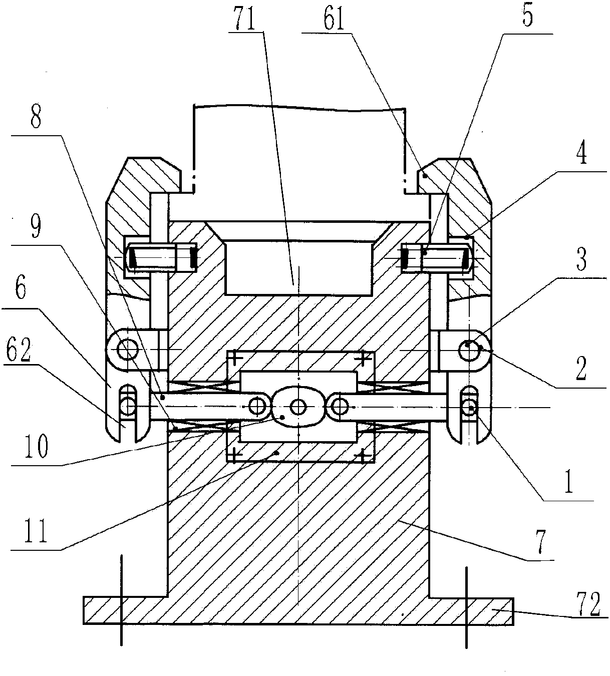
[0018] Such as figure 1 A pneumatic cam quick clamp shown includes bracket 2, pin I1, pin II3, return spring 5, pressure plate 6, base 7, push rod 8, linear bearing 9, double-sided cam 10 and rotary cylinder 11.

[0019] The rotary cylinder 11 is installed on the base 7, the double-sided cam 10 is installed on the rotary cylinder 11, and the base 7 on both sides of the double-sided cam 10 is respectively provided with a linear bearing 9, and the linear bearing 9 is provided with a push rod 8, and the push rod One end of 8 is in contact with double-sided cam 10, and the other end is provided with pin I1. Both sides of the base 7 are respectively provided with pressure plates 6, one end of the pressure plate 6 has a notch structure 62, and the other end is provided with a chuck 61, the chucks 61 of the two pressure plates 6 are arranged oppositely, and the pressure plate 6 is close to the groove structure. One side of 62 is provided with a pin II3, and the pin II3 movably conne...


PUM


Abstract

The invention discloses a quick pneumatic cam clamping device comprising a base, a rotary cylinder arranged on the base, a double-sided cam mounted on the cylinder and push rods. The push rods are located on two sides of the double-sided cam and movably connected with the base, one end of each push rod is in contact connection with the double-sided cam, pressing plates are arranged on two sides of the base and movably connected with supports which are fixedly connected on the base, one end of each pressing plate is a clamping part, the other end of each pressing plate is movably connected with the other end of the corresponding push rod, and a return spring is arranged on each pressing plate and between one side close to the clamping part and the position corresponding to the base. The clamping apparatus can improve production efficiency significantly, is applicable to batch production and has the advantages of high clamping force, rapid action, convenience in operation and the like.

Description

technical field [0001] The invention relates to a pneumatic cam quick clamper, which is mainly used in the working occasions where the workpiece needs to be quickly clamped when the workpiece is milled by a numerical control milling machine and an ordinary milling machine and the workpiece is welded. Background technique [0002] CNC milling machines and ordinary milling machines need to clamp the workpiece when milling or welding the workpiece. The current clamping method is to rely on the clamping plate clamping or the centering clamping of the three-jaw chuck. This clamping method takes a long time to clamp. It affects production efficiency, especially in the process of repeated trial and clamping in mass production, not only affects production and processing efficiency, but also affects the centering accuracy of the workpiece, and reduces the machining accuracy of the workpiece. Therefore, it is a technical problem that those skilled in the art urgently need to solve to ...

Claims


Application Information

Patent Timeline
IPC IPC(8): B23Q3/08
CPCB23K37/04B23Q3/08B23Q2703/04
Inventor 宋宝炜耿秋颖张续军宋晶晶
Owner SHENYANG AIRCRAFT CORP
Features
  • Generate Ideas
  • Intellectual Property
  • Life Sciences
  • Materials
  • Tech Scout
  • Unparalleled Data Quality
  • Higher Quality Content
  • 60% Fewer Hallucinations
Learn More