Foam metal radiator for LED (light emitting diode) lamp

A metal foam and LED lamp technology, applied in lighting and heating equipment, cooling/heating devices of lighting devices, lighting devices, etc., can solve problems such as attenuation, longer wavelength of light emitted by devices, and shorter service life, and achieve thermal conductivity High, large specific surface area, good heat dissipation effect

Inactive Publication Date: 2014-12-10
HEFEI HUICAI ELECTRONICS TECH
View PDF5 Cites 1 Cited by
  • Summary
  • Abstract
  • Description
  • Claims
  • Application Information

AI Technical Summary

Problems solved by technology

At present, LED lamps have been widely used in daily life as optoelectronic devices, but most of the electric energy is dissipated in the form of heat during the working process. Since the heat is mainly generated by the chip, and the chip area is small, as the input power increases, the on-chip The accumulated heat will be more and more, and the temperature will be higher a

Method used


Image

  • Foam metal radiator for LED (light emitting diode) lamp

Examples


Embodiment Construction

[0009] The present invention will be further described below with reference to the accompanying drawings.

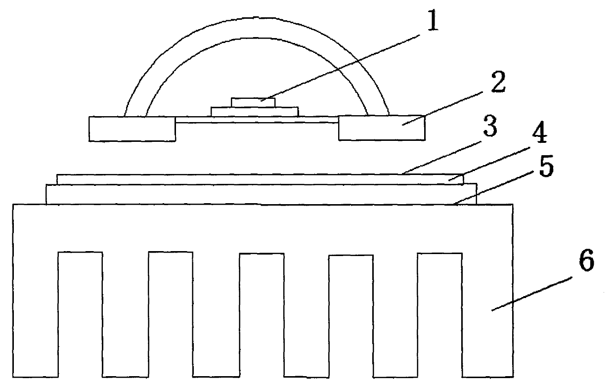
[0010] Such as figure 1 As shown, a metal foam heat sink for LED lamps includes LED chips (1), metal foam heat sink blocks (2), aluminum substrates (4) and heat sinks (6), and the LED chips (1) are arranged on the In the metal foam heat dissipation block (2), the metal foam heat dissipation block (2) is welded on the aluminum substrate (4) by solder (3), and the aluminum substrate (4) is fixed on the aluminum substrate (4) by thermally conductive glue (5) on the radiator (6).

[0011] The heat generated by the LED chip (1) is conducted from the metal foam heat sink (2) at the lower part, passes through the solder (3) to the aluminum substrate (4), and then reaches the heat sink (6) through the thermally conductive adhesive (5), and finally passed into the air.


PUM


Abstract

The invention relates to a foam metal radiator for an LED (light emitting diode) lamp. The foam metal radiator for the LED lamp comprises an LED chip, a foam metal heat dissipation block, an aluminum substrate and a radiator body, wherein the LED chip is arranged in the foam metal heat dissipation block; the foam metal heat dissipation block is welded to the aluminum substrate through welding flux; and the aluminum substrate is fixed on the radiator body through heat-conducting glue. By the foam metal radiator for the LED lamp, heat of the LED chip can be delivered with the aid of characteristics of large specific surface area and high heat conductivity of foam metal, and the heat dissipation effect is high.

Description

technical field [0001] The invention relates to a heat sink for LED lamps, in particular to a foam metal heat sink for LED lights. Background technique [0002] LED refers to light-emitting diode, which is a semiconductor electronic component that can convert electrical energy into light energy. At present, LED lamps have been widely used in daily life as optoelectronic devices, but most of the electric energy is dissipated in the form of heat during the working process. Since the heat is mainly generated by the chip and the chip area is small, as the input power increases, the on-chip The accumulated heat will be more and more, and the temperature will be higher and higher, especially for high-power LED lamps. The current working temperature exceeds the load temperature of the chip, which will rapidly reduce the luminous efficiency of the LED lamp and produce obvious attenuation. At the same time, the device The wavelength of light emission becomes longer, and the color is...

Claims


Application Information

Patent Timeline
IPC IPC(8): F21V29/00F21Y101/02
Inventor 卢继乾石井艳
Owner HEFEI HUICAI ELECTRONICS TECH
Why Eureka
Try Eureka