Three-dimensional digital imaging method based on structured light gray level vector
A three-dimensional digital and imaging method technology, applied in the field of three-dimensional imaging, can solve the problems of slow measurement speed and large amount of calculation, and achieve the effect of short time consumption, simple calculation and high spatial resolution
- Summary
- Abstract
- Description
- Claims
- Application Information
AI Technical Summary
Problems solved by technology
Method used
Image

Examples
Embodiment 1
[0057] This embodiment describes the three-dimensional digital imaging device matched with the method of the present invention.
[0058] The three-dimensional digital imaging device matched with the method of the present invention mainly includes a digital projection lighting transmitter, an image sensing receiver and an image processor. Among them, the digital projection lighting transmitter can be a digital liquid crystal projection device (LCD projector), a digital micromirror projection device (DMD projector) or a silicon substrate liquid crystal projection device (LCOS projector), which can be easily generated by a computer image processing system. Combination of gray scale code and binary code for stripe pattern and write into digital projection device. The image sensing receiver includes an optical imaging lens and a photodetector. The optical imaging lens can be an imaging lens or lens group with a fixed focal length or a variable focal length, a binary optical imaging...
Embodiment 2
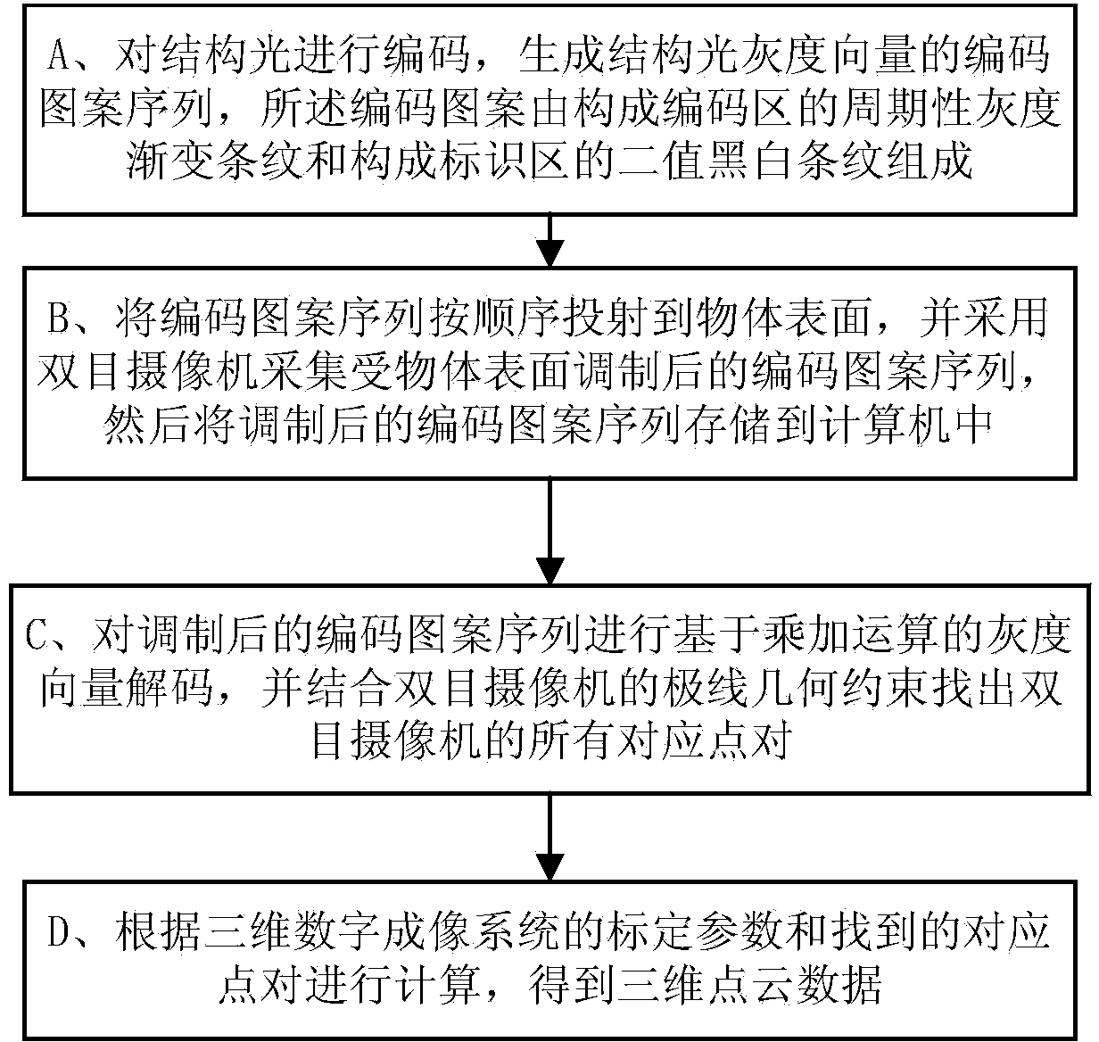
[0060] Such as Figure 5 In the shown structured light gray vector imaging system, the computer or digital signal processor of the image processor 104 generates a projection coded fringe pattern based on the gray vector three-dimensional digital imaging method. Each coding pattern is composed of coding stripes constituting the coding area and binary black and white marking stripes constituting the marking area; inside the coding area are coding stripes whose gray value increases and decreases alternately, and the gradient of the gray value can be used to distinguish between the same coding stripes different pixels within. In the present invention, each coded stripe width is called a period. There are only two cases of gray value in the identification area: 0 (black) and 1 (white). Its function is to combine the gray value of the coding area to form a unique vector, so as to distinguish pixels in different periods. . In the pattern sequence, the coding area of each pattern...
Embodiment 3
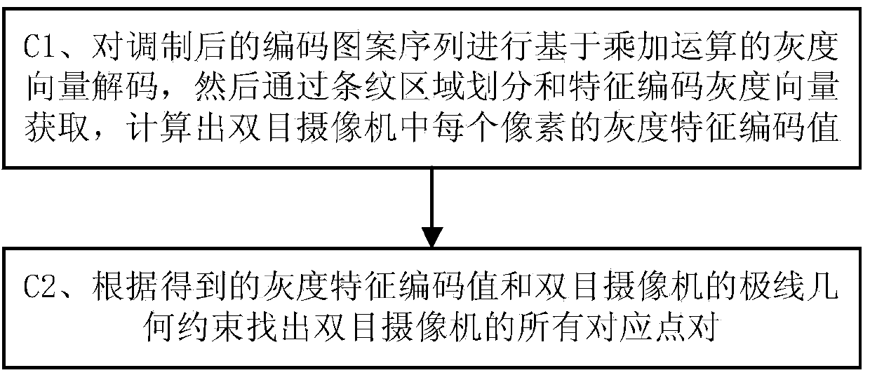
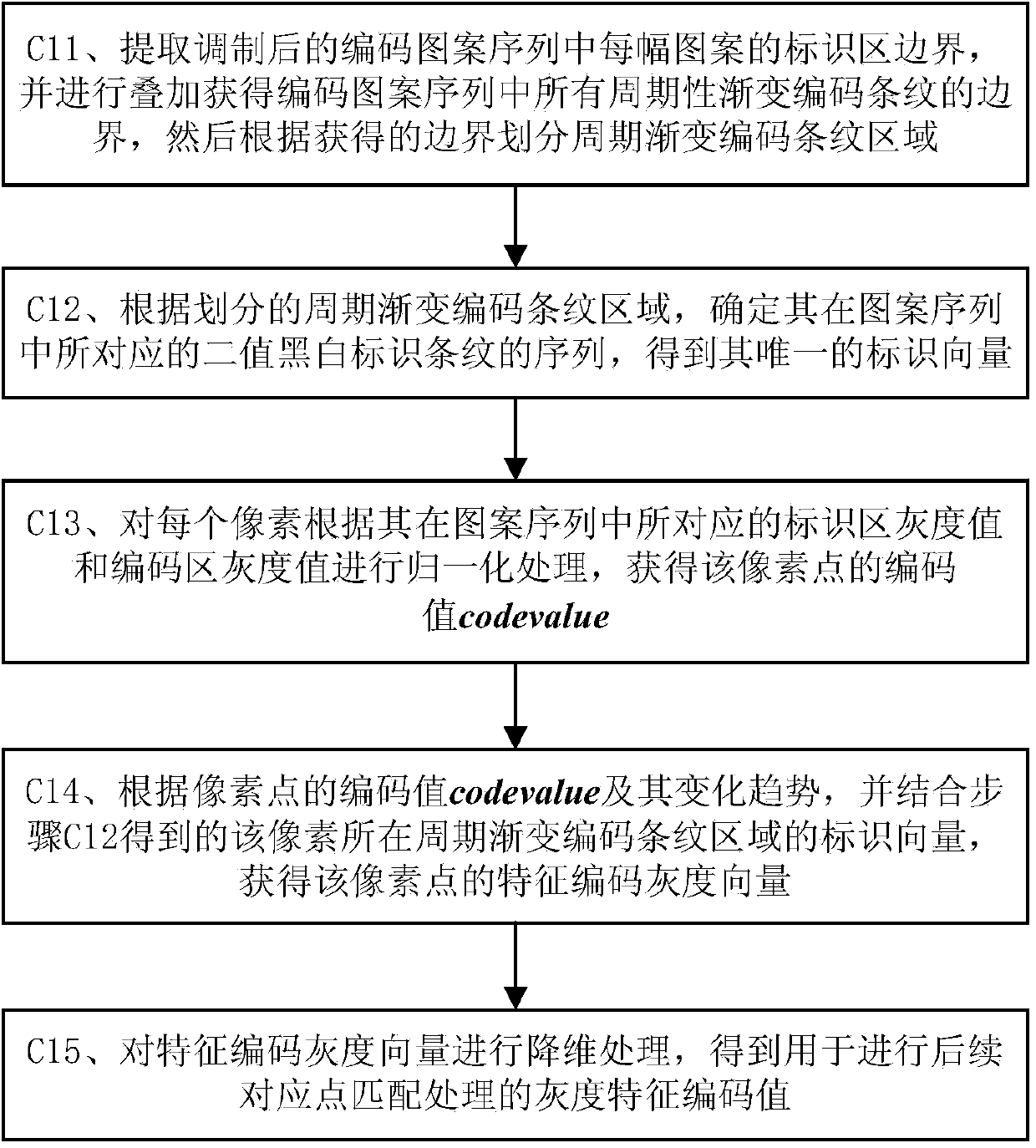
[0069] This embodiment describes the corresponding point search process based on epipolar geometric constraints and coded values in the present invention.
PUM
 Abstract
Description
Claims
Application Information
 - Generate Ideas
- Intellectual Property
- Life Sciences
- Materials
- Tech Scout
- Unparalleled Data Quality
- Higher Quality Content
- 60% Fewer Hallucinations
Browse by: Latest US Patents, China's latest patents, Technical Efficacy Thesaurus, Application Domain, Technology Topic, Popular Technical Reports.
© 2025 PatSnap. All rights reserved.Legal|Privacy policy|Modern Slavery Act Transparency Statement|Sitemap|About US| Contact US: help@patsnap.com