A very low frequency radio wave shielding test device

A testing device and extremely low frequency technology, which is applied in the direction of measuring devices, measuring electrical variables, instruments, etc., can solve the problems of difficulty in strict index detection, difficulty in simulating the physical environment of outer space and low-interference physical background, etc., to achieve overall airtight and Strong shielding performance, small leakage of component pores, good effect

Active Publication Date: 2017-01-25
NAT SPACE SCI CENT CAS
View PDF5 Cites 0 Cited by
  • Summary
  • Abstract
  • Description
  • Claims
  • Application Information

AI Technical Summary

Problems solved by technology

However, in the current laboratory environment, it is difficult to simulate the real physical environment and low-interference physical background of outer space, and it is even more difficult to achieve a higher standard of strict index detection
The background low-frequency electromagnetic noise is less than 10 -5 nT / (Hz) 1 / 2 For example, in order to realize the strict detection and calibration of the low-frequency radio wave detector equipment in this band, it is necessary to have a device that can shield the extremely low-frequency radio wave and at the same time perform basic testing, screening and calibration of the sensor search coil of the detector. At present, only the unconventional metal shielding tube thickened shielding method can be used in the laboratory to simulate the space environment that meets this electromagnetic index.

Method used


Image

  • A very low frequency radio wave shielding test device
  • A very low frequency radio wave shielding test device
  • A very low frequency radio wave shielding test device

Examples


Embodiment Construction

[0039] The ultra-low radio wave shielding testing device of the present invention will be described in detail below with reference to the accompanying drawings and embodiments, and will be implemented through the following technical solutions.

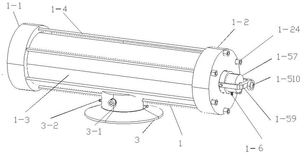
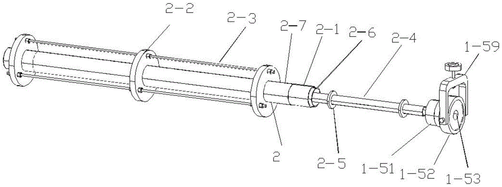
[0040] like figure 1 and image 3 As shown, an extremely low radio wave shielding test device according to an embodiment of the present invention includes: a radio wave shielding cylinder 1 and a test coil 2 in the cylinder, wherein the test coil 2 in the cylinder is located in the radio wave shielding cylinder 1 .

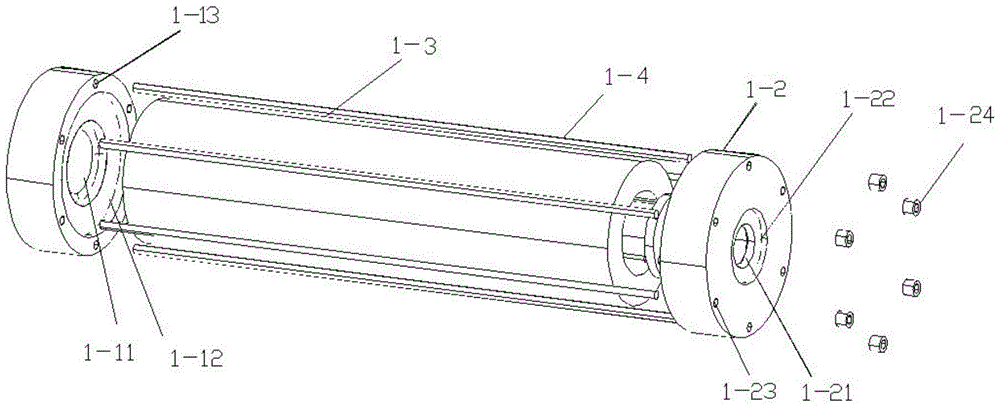
[0041] like figure 1 and Figure 4 As shown, the radio wave shielding cylinder 1 includes: a first cylinder end cover 1-1, a second cylinder end cover 1-2, a thick-walled metal tube 1-3, a screw 1-4, a double hole cover 1-5 and a shielding cover 1 -57; the first cylinder end cap 1-1 and the second cylinder end cap 1-2 are located at both ends of the thick-walled metal tube 1-3; the double hole cap 1-5 closes the first c...


PUM


Abstract

Disclosed is an extremely-low-frequency radio wave shielding test device. The device comprises a radio wave shielding cylinder and an in-cylinder test coil, the in-cylinder test coil is located in the radio wave shielding cylinder, the radio wave shielding cylinder comprises a first cylinder end cover, a second cylinder end cover, a thick-wall metal tube, screws, a dual hole cover and a shielding cover, the first cylinder end cover, the thick-wall metal tube and the second cylinder end cover are fixed into a whole through the screws to form a shielding cavity body portion of the extremely-low-frequency radio wave shielding test device, a disc support supporting a test solenoidal coil, a protective casing located outside the test solenoidal coil, the test solenoidal coil and a round tube used for winding of the test solenoidal coil are distributed in the in-cylinder test coil from outside to inside, a tube support and a test tube are arranged in a hole of the round tube, and the tube support is used for supporting the test tube. The extremely-low-frequency radio wave shielding test device is wide in shielding range, integrally airtight and high in shielding properties, good in shielding effect on medium and low frequency band radio waves, and applicable to professional laboratories.

Description

technical field [0001] The invention relates to the field of radio wave shielding, in particular to an extremely low frequency radio wave shielding test device used as an electromagnetic detection screening test for each coil component on a three-dimensional search coil sensor of a satellite low-frequency electromagnetic wave detector. Background technique [0002] Low-frequency radio wave shielding technology refers to: using the high conductivity of good conductive materials and the characteristics of an equipotential shielding body to form a relatively clean electromagnetic space area, which is used to shield the external alternating radio waves in a specific space area to its internal interference such as leakage of radio waves. . For extremely low frequency radio waves of the order of 10Hz, due to the unfavorable factors such as the obvious increase of the skin depth of the radio wave leaking into the shielding conductor layer or the obvious thickening of the surface cu...

Claims


Application Information

Patent Timeline
Patent Type & Authority Patents(China)
IPC IPC(8): G01R35/00
Inventor 董伟沈超陈涛王乃泉罗静
Owner NAT SPACE SCI CENT CAS
Why Eureka
Try Eureka