
Design method for optimizing filter to suppress switching noise

An optimized design and switching noise technology, applied in the direction of output power conversion devices, electrical components, etc., can solve problems such as affecting normal work and generating electromagnetic interference, and achieve the effects of reducing heat dissipation costs, high conversion efficiency, and solving electromagnetic interference

Inactive Publication Date: 2014-12-10
SHANDONG CHAOYUE DATA CONTROL ELECTRONICS CO LTD
View PDF5 Cites 4 Cited by
  • Summary
  • Abstract
  • Description
  • Claims
  • Application Information

AI Technical Summary

Problems solved by technology

[0002] Compared with linear power supply, switching power supply has the characteristics of high efficiency and miniaturization, which is very in line with the needs of modern industry. It is widely used in various fields such as computer and its peripheral equipment, communication, automatic control, and household appliances; its main disadvantage compared with linear power supply is Electromagnetic interference will be generated. The main reason is that the switching power supply controls the high-speed turn-on and cut-off of the transistor through the circuit. The high-speed turn-on and turn-off of the transistor will cause changes in voltage and current. The power switch tube causes rapid changes in voltage and current during the switching process. Spike interference and resonance interference are generated through other components in the circuit, and these noises will affect the normal operation of the internal circuit of the system and other systems through coupling channels such as conduction and radiation.

Method used


Image

  • Design method for optimizing filter to suppress switching noise

Examples


Embodiment Construction

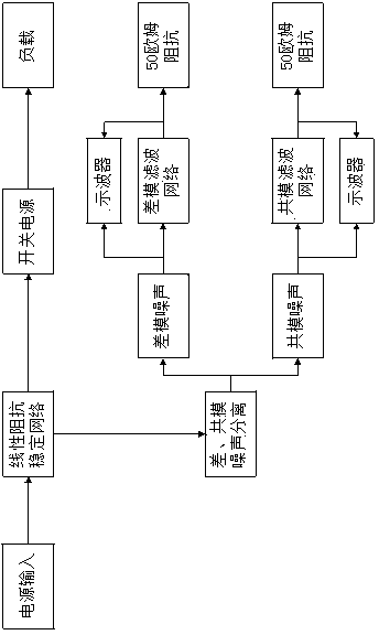
[0012] A filter optimization design method for suppressing switching noise of the present invention will be described in detail below with reference to the accompanying drawings.

[0013] When a product uses a switching power supply, it will inevitably generate noise, which can be divided into common-mode noise and differential-mode noise according to its transmission form. Differential mode noise is the noise current flowing between the signal line and the signal ground (or between the live line and the neutral line of the power line); while the common mode noise is the noise current flowing in the loop formed between the cable and the ground. A filter is a two-port network, which has the characteristic of frequency selection. Using the principle of signal impedance mismatch, some frequencies can be passed smoothly, while other frequencies are blocked.

[0014] When the switching power supply is close to full-load output, its peak interference and harmonic interference will b...


PUM


Abstract

The patent is a design method for optimizing a filter to suppress switching noise. The method includes the steps of supplying power to a switching power supply through a line impedance stabilization network, using a purely resistive load as a load end and adding the load to the maximum output load of the switching power supply and separating common mode and differential mode noise which are produced by a switch line via a differential mode and common mode noise separator and the line impedance stabilization network. Furthermore, the differential mode noise passes a differential mode filtering network carrier board, network effect of differential mode filtering is detected by the use of an oscilloscope, output and input voltage ratio of filter network noise of the differential mode are compare, insertion loss value of the differential mode filtering network is roughly estimated, standard limit requirements are met with a minimum of differential mode filtering devices, and filter optimization is achieved. Meanwhile, common mode noise passes a common mode filtering network carrier board, network effect of common mode filtering is detected by the use of the oscilloscope, output and input voltage ratio of filter network noise of the common mode are compare, insertion loss value of the common mode filtering network is roughly estimated, standard limit requirements are met with a minimum of common mode filtering devices, and filter optimization is achieved.

Description

technical field [0001] The invention relates to the field of computer application technology, in particular to a filter optimization design method for suppressing switching noise. Background technique [0002] Compared with linear power supply, switching power supply has the characteristics of high efficiency and miniaturization, which is very in line with the needs of modern industry. It is widely used in various fields such as computer and its peripheral equipment, communication, automatic control, and household appliances; its main disadvantage compared with linear power supply is Electromagnetic interference will be generated. The main reason is that the switching power supply controls the high-speed turn-on and cut-off of the transistor through the circuit. The high-speed turn-on and turn-off of the transistor will cause changes in voltage and current. The power switch tube causes rapid changes in voltage and current during the switching process. Spike interference and ...

Claims


Application Information

Patent Timeline
IPC IPC(8): H02M1/44H02M1/12H02M1/14
Inventor 徐成焱耿士华刘泽
Owner SHANDONG CHAOYUE DATA CONTROL ELECTRONICS CO LTD
Learn More