Resonant converter and method for controlling same

A technology of resonant converters and transformers, used in control/regulation systems, conversion of DC power input to DC power output, instruments, etc., can solve the problems of reducing reliability and efficiency, aggravating switching device stress, and high voltage stress of switching devices. To achieve the effect of simple design and implementation, easy to optimize design, and high conversion efficiency

Inactive Publication Date: 2014-12-10
NANJING UNIV OF AERONAUTICS & ASTRONAUTICS
View PDF6 Cites 18 Cited by
  • Summary
  • Abstract
  • Description
  • Claims
  • Application Information

AI Technical Summary

Problems solved by technology

[0003] Although traditional isolated DC converters, such as forward converters, flyback converters, push-pull converters, half-bridge converters, and full-bridge converters, can achieve electrically isolated power conversion, they generally have the following problems: switching The voltage stress of the device is high, especially the voltage stress of the rectifier diode on the secondary side of the converter is much higher than the output voltage; the voltage spike and oscillation of the switching device caused by the leakage inductance of the transformer further aggravates the stress of the switching device and reduces the reliability and efficiency
However, the LLC resonant converter needs to adjust the output voltage by changing the switching frequency. When the load or input voltage fluctuates, the switching frequency needs to change in a wide range, which poses a challenge to the analysis, design and implementation of the converter, especially the magnetic The optimal design and implementation of devices has brought great difficulties and challenges, and the realization of variable frequency control is much more complicated than conventional fixed frequency control, and it has also caused great difficulties in the modeling and analysis of converters.

Method used


Image

  • Resonant converter and method for controlling same
  • Resonant converter and method for controlling same
  • Resonant converter and method for controlling same

Examples


Embodiment Construction

[0021] The technical solutions of the present invention will be described in detail below in conjunction with the accompanying drawings and embodiments.

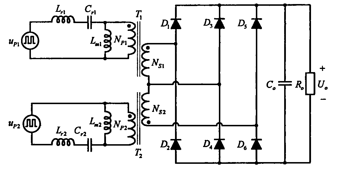
[0022] as attached figure 1 As shown, the resonant converter of the present invention is composed of the first high frequency rectangular wave voltage source (u P1 ), the second high frequency rectangular wave voltage source (u P2 ), the first resonant inductance (L r1 ), the second resonant inductance (L r2 ), the first resonant capacitor (C r1 ), the second resonant capacitor (C r2 ), the first main inductance (L m1 ), the second main inductance (L m2 ), the first transformer (T 1 ), the second transformer (T 2 ), the first diode (D 1 ), the second diode (D 2 ), the third diode (D 3 ), the fourth diode (D 4 ), the fifth diode (D 5 ), the sixth diode (D 6 ), output filter capacitor (C o ) and load (R o ) form, where the first transformer (T 1 ) including the first primary winding (N P1 ) and the first seco...


PUM


Abstract

The invention discloses a resonant converter and a method for controlling the same, and belongs to the technical field of power electronics converters. The resonant converter comprises two high-frequency square-wave voltage sources (u<P1> and u<P2>), two resonant inductors (L<r1> and L<r2>), two resonant capacitors (C<r1> and C<r2>), two main inductors (L<m1> and L<m2>), two transformers (T<1> and T<2>), six diodes (D<1>, D<2>, D<3>, D<4>, D<5> and D<6>), an output filter capacitor (C<o>) and a load (R<o>). The frequencies and the pulse widths of the two high-frequency square-wave voltage sources are identical to one another, the frequencies of the two high-frequency square-wave voltage sources are fixed, and output voltages can be adjusted under phase-shift control between the two high-frequency square-wave voltage sources. The resonant converter and the method have the advantages that two resonant networks which are formed by the resonant inductors, the resonant capacitors and the main inductors constantly work at the fixed frequencies, and accordingly the resonant converter is simple in control and easy to implement; soft switching on all switch tubes and the diodes of the converter can be implemented in full-voltage and load ranges, high-frequency and efficient power conversion can be implemented, the sizes of the inductors and the sizes of the transformers can be effectively reduced, and high-power density effects can be realized.

Description

technical field [0001] The invention relates to a resonant converter and a control method thereof, belonging to the technical field of power electronic converters. Background technique [0002] Isolated converters are suitable for applications where electrical isolation is required for input and output, and are widely used in new energy power generation, industry, civil, aerospace and other fields. [0003] Although traditional isolated DC converters, such as forward converters, flyback converters, push-pull converters, half-bridge converters, and full-bridge converters, can achieve electrically isolated power conversion, they generally have the following problems: switching The voltage stress of the device is high, especially the voltage stress of the rectifier diode on the secondary side of the converter is much higher than the output voltage; the voltage spike and oscillation of the switching device caused by the leakage inductance of the transformer further aggravates th...

Claims


Application Information

Patent Timeline
Patent Type & Authority Applications(China)
IPC IPC(8): H02M3/335H02M7/06
CPCY02B70/10
Inventor 吴红飞夏天牟恬恬邢岩
Owner NANJING UNIV OF AERONAUTICS & ASTRONAUTICS
Why Eureka
Try Eureka