Current homogenizing magnetic field structure of multistage cusped magnetic field plasma thruster
A plasma and tangent magnetic field technology, applied in the field of current homogenized magnetic field structure, can solve the problems of high magnetic field strength, uneven electron distribution, large magnetic interface angle, etc., and achieve the effect of reducing material and processing costs
- Summary
- Abstract
- Description
- Claims
- Application Information
AI Technical Summary
Problems solved by technology
Method used
Image
Examples
specific Embodiment approach 1
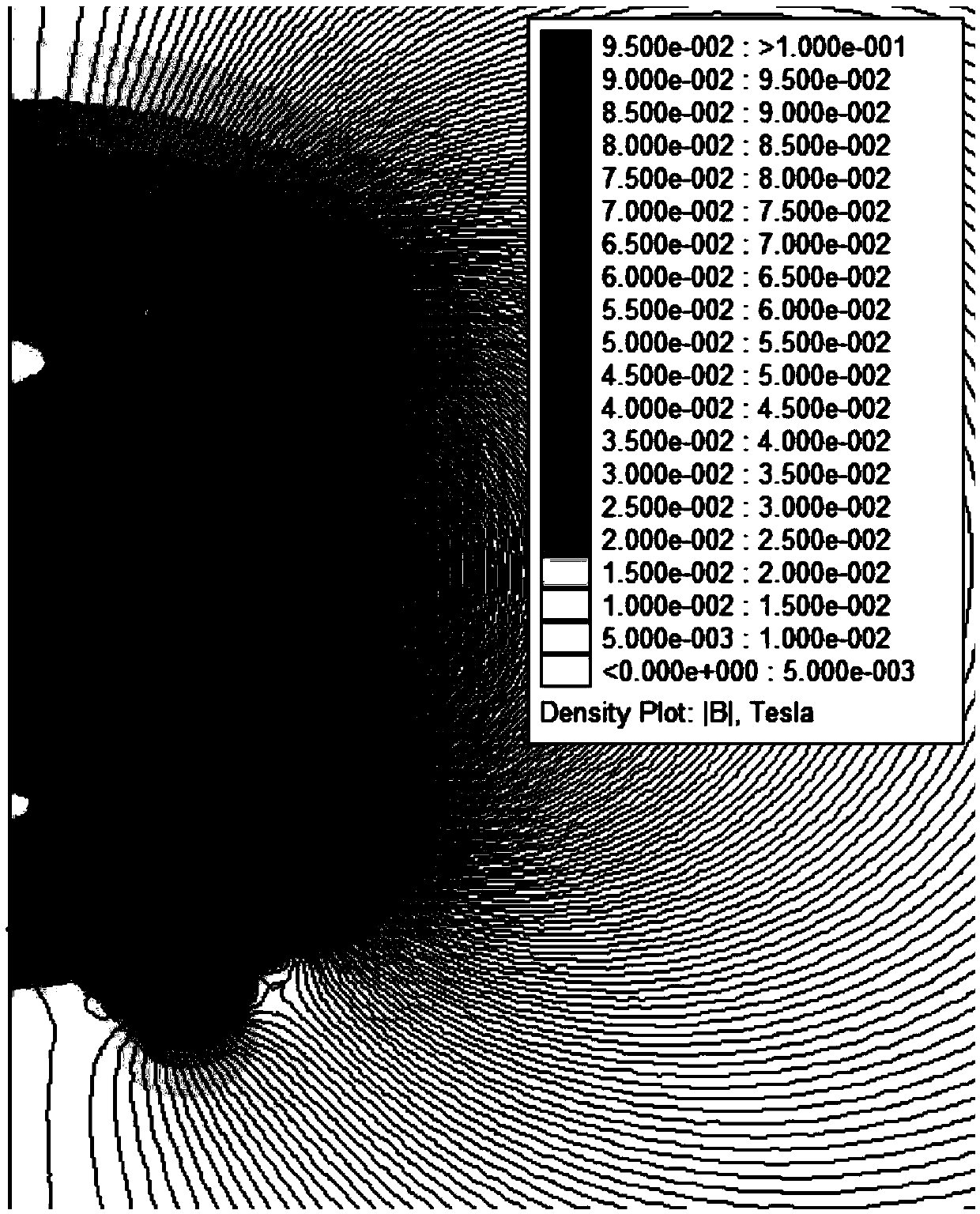
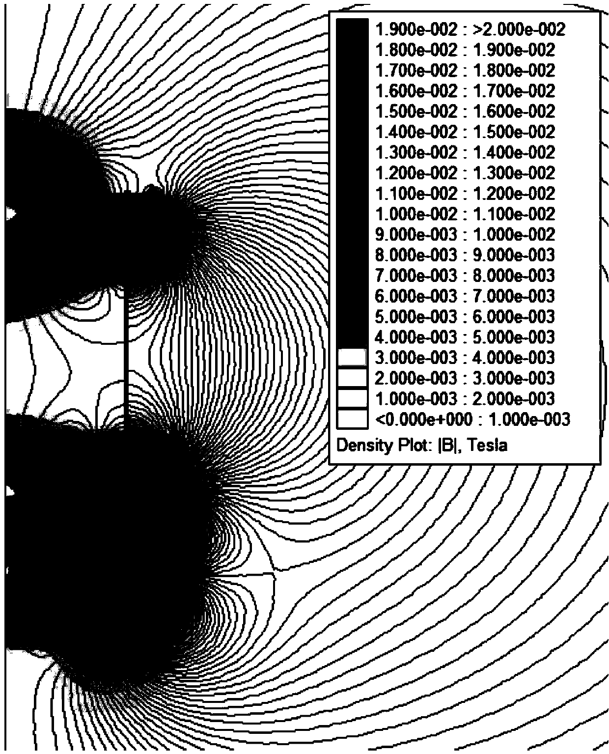
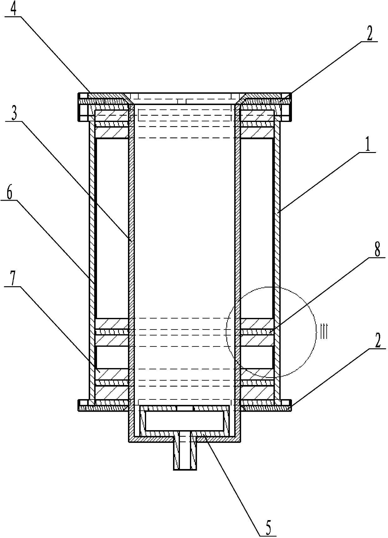
[0026] Specific implementation mode one: combine Figure 3-Figure 8 This embodiment is described. The current homogenizing magnetic field structure of a multi-stage cusp magnetic field plasma thruster in this embodiment includes a casing 1, two fixed end plates 2, a ceramic sleeve 3, an outlet ceramic gasket 4, an anode and Breather 5, multiple magnetic field guide rings 6, multiple annular permanent magnets 7 and multiple magnetic conduction rings 8, two fixed end plates 2 are respectively installed on the upper and lower surfaces of the shell 1, and the ceramic sleeve 3 is vertically mounted on the shell 1, and the lower end of the ceramic sleeve 3 protrudes from the shell 1, the anode and the breather 5 are installed at the bottom of the inner wall of the ceramic sleeve 3 and extend out of the bottom end of the ceramic sleeve 3, the inner wall of the shell 1 and the ceramic sleeve 3 A magnetic conduction ring 8 is respectively provided on the upper and lower end surfaces be...
specific Embodiment approach 2
[0038] Specific implementation mode two: combination Figure 3-Figure 8 To describe this embodiment, the annular permanent magnet 7 of this embodiment is made of samarium and cobalt materials in a ratio of 2:17. Such setting can make the permanent magnet material have higher coercive force, can generate a stronger magnetic field, and can withstand the higher temperature generated when the thruster is working. Other compositions and connections are the same as in the first embodiment.
specific Embodiment approach 3
[0039] Specific implementation mode three: combination Figure 3-Figure 8 Describe the present embodiment, the magnetic field guide ring 6 of the present embodiment is an annular structure, and the outer diameter of the magnetic field guide ring 6 is identical with the outer diameter of the annular permanent magnet 7, and the upper and lower end faces of the magnetic field guide ring 6 are respectively connected to the outer diameter of the annular permanent magnet 7. Face fit. In this way, the magnetic field guide ring can connect the magnetic fields generated by the annular permanent magnets on the upper and lower end faces into a magnetic flux circuit, and at the same time replace the original permanent magnet mechanism, weaken the magnetic field intensity in the center of the channel, and make the magnetic field lines in the channel outward Expansion, which expands the movement path of electrons, broadens the ionization range, and increases the ionization rate of the gas w...
PUM
| Property | Measurement | Unit |
|---|---|---|
| The inside diameter of | aaaaa | aaaaa |
| Outer diameter | aaaaa | aaaaa |
| Height | aaaaa | aaaaa |
Abstract
Description
Claims
Application Information
 - R&D
- Intellectual Property
- Life Sciences
- Materials
- Tech Scout
- Unparalleled Data Quality
- Higher Quality Content
- 60% Fewer Hallucinations
Browse by: Latest US Patents, China's latest patents, Technical Efficacy Thesaurus, Application Domain, Technology Topic, Popular Technical Reports.
© 2025 PatSnap. All rights reserved.Legal|Privacy policy|Modern Slavery Act Transparency Statement|Sitemap|About US| Contact US: help@patsnap.com


