
Sludge desanding device, pretreatment device and method for municipal sewage plant

A pretreatment device and technology for urban sewage, applied in the direction of water/sludge/sewage treatment, sludge treatment, chemical instruments and methods, etc., can solve the problem of poor sludge quality in cement plants, no effect, impure biogas, etc. problems, to achieve the effect of increasing the content of organic matter, facilitating biological treatment, and avoiding sediment deposition

Active Publication Date: 2014-12-17
三川德青工程机械有限公司
View PDF10 Cites 1 Cited by
  • Summary
  • Abstract
  • Description
  • Claims
  • Application Information

AI Technical Summary

Problems solved by technology

[0005] 1. Sewage treatment system equipment flow-through parts (pump casing, pipes and elbows) are severely worn, and equipment operation and maintenance costs are high; especially soft fiber substances such as hair in sewage can easily cause equipment damage
[0006] 2. The sludge quality is poor and the cement plant is unwilling to accept it, so the sewage plant has to pay a higher sludge disposal fee to the cement plant
[0007] 3. According to the general sewage treatment process, the primary sludge and the remaining sludge should enter the digester together for digestion. Due to its high sand content, the biogas produced by it is impure and cannot be used as a resource.
[0008] Various sewage treatment plants have carried out transformation on the original basis, or built advection grit chambers, or transformed the original gas type into a bottom stagnation type for sand-water separation, but none of them have achieved satisfactory results

Method used


Image

  • Sludge desanding device, pretreatment device and method for municipal sewage plant
  • Sludge desanding device, pretreatment device and method for municipal sewage plant
  • Sludge desanding device, pretreatment device and method for municipal sewage plant

Examples


Embodiment 1

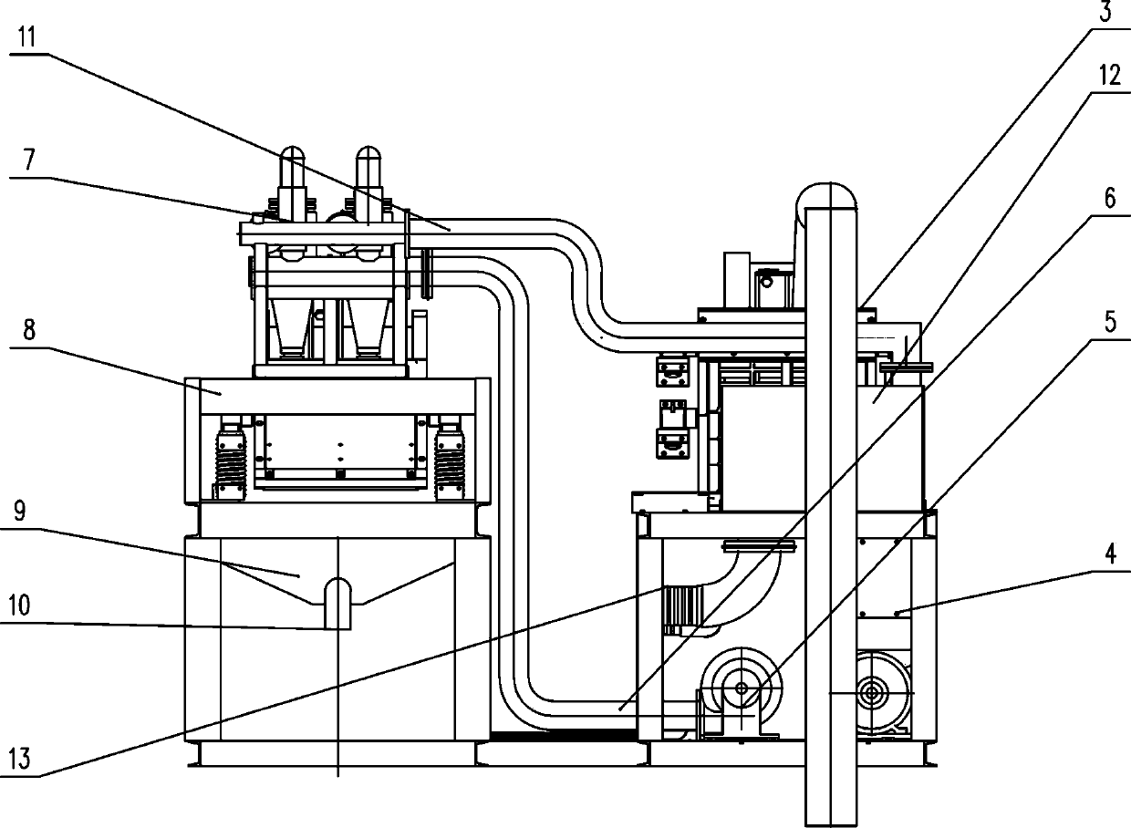
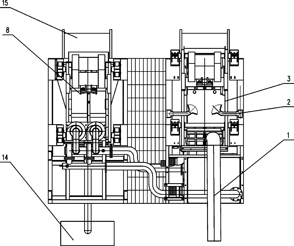
[0040] Such as Figure 1~5 Among them, a sludge removal device for urban sewage treatment plants, including a pretreatment device and a main separation device, the pretreatment device is a pre-screen 3, the top of the pre-screen 3 is provided with multiple rows of bar devices, and the bar devices are along the Arranged obliquely along the flow direction of the sludge, in the rod device, one end of a plurality of rods 31 is fixedly installed on the base 32, and the other end is a free end, and arranged along the flow direction of the sludge. Such as image 3 As shown in , the base 32 is positioned at the upstream of the sludge flow, and the free end of the root bar 31 is positioned at the downstream of the sludge flow. Adopting this structure is convenient for cleaning soft fibrous substances such as hair entangled on the bar 31 .

[0041] The angle a between the bars 31 and the horizontal plane is 0-15 degrees, preferably 8-10 degrees in this example, and the distance between...

Embodiment 2

[0051] Such as Figure 3-5 Among them, a pretreatment device of a sludge desanding device in an urban sewage treatment plant, the top of the pre-screen 3 is provided with multiple rows of bar devices, and the bar devices are arranged obliquely along the flow direction of the sludge. Among the bar devices, there are multiple One end of the bar 31 is fixedly installed on the base 32, and the other end is a free end, and is arranged along the flow direction of the sludge.

[0052] The angle between the rods 31 and the horizontal plane is 0-15 degrees, and the distance between the rods 31 is 2-10 mm.

[0053] The base 32 is connected with the frame 33 of the pre-screen 3 through an adjustable inclination angle.

[0054] Both sides of the base 32 are connected to the frame 33 by adjusting bolts 34 , and a wedge 35 is arranged below the base 32 . This device is used as a core component in Embodiment 1, and the parts that are not described in detail are the same as those in Embodim...

Embodiment 3

[0056] A method for removing sand from urban sewage treatment plant sludge, comprising the following steps:

[0057] 1. Pretreatment

[0058] On the basis of the equipment in Examples 1 and 2, the primary sludge is removed through pre-screening 3 to remove soft fibrous matter and large-grained sand in the primary sludge, and the underflow under the pre-screening 3 screen enters the slurry storage tank 4; pre-screening 3 A flow meter is installed on the slurry inlet pipeline to measure the slurry.

[0059] The top of the pre-screen 3 is provided with multiple rows of rod devices, which are arranged obliquely along the flow direction of the sludge. In the rod device, one end of a plurality of rods 31 is fixedly installed on the base 32, and the other end is a free end. It is arranged along the flow direction of the sludge, and a hydraulic flushing device 2 is installed above the pre-screen 3 to cooperate with the flushing; the soft fiber materials such as hair and large particl...


PUM


Abstract

The invention discloses a sludge desanding device for a municipal sewage plant, and the sludge desanding device comprises a pretreatment device and a main separating device, the pretreatment device is a prescreening sieve whose top is provided with multiple rows of rod devices obliquely arranged along the sludge flowing direction, in the rod device, ends of multiple rods are fixedly installed on a substrate while their other ends are regarded as free ends arranged along the sludge flowing direction. A sludge desanding method for the municipal sewage plant comprises the following steps of: firstly, preprocessing; removing soft fibers from primary sludge through the prescreening sieve and guiding underflow under the prescreening sieve into a slurry-storing tank; secondly, performing solid-liquid separation with hydraulic cyclone; thirdly, screening with a dewatering screen; desanding sludge from the municipal sewage plant through the mentioned steps. Through utilization of the device and the method, hairs and other soft fibers from the sludge can be effectively removed, thereby reducing gravels in the sludge, improving the content of the organic matter from the treated sludge, reducing the sludge concentration and preventing sediment from deposition.

Description

technical field [0001] The invention relates to the field of primary sludge treatment in urban sewage treatment plants, in particular to a sludge desanding device, pretreatment device and method for urban sewage treatment plants. Background technique [0002] In recent years, with the rapid development of society, the amount of urban sewage is also increasing day by day, and due to the society's high attention to environmental protection, the number of sewage plants is also increasing rapidly, and sludge as a by-product of sewage plants is also inevitable. Substantial growth. How to economically, effectively and safely treat and dispose of the large amount of sludge produced by these sewage plants has become an urgent problem to be solved in the field of sewage treatment in our country. In the process of sewage treatment, the accumulation of inert inorganic substances (silt) in the sewage treatment system not only affects the sewage treatment effect, but also the accumulati...

Claims


Application Information

Patent Timeline
Patent Type & Authority Applications(China)
IPC IPC(8): C02F11/00
Inventor 张沛强甘虎肖桂华陶鹏
Owner 三川德青工程机械有限公司
Learn More