Two-Shaft Gas Turbine

A gas turbine, dual-shaft technology, used in gas turbine installations, mechanical equipment, engine control, etc.

Active Publication Date: 2014-12-17
MITSUBISHI POWER LTD
View PDF5 Cites 8 Cited by
  • Summary
  • Abstract
  • Description
  • Claims
  • Application Information

AI Technical Summary

Problems solved by technology

However, since the inlet temperature of the low-pressure turbine has risen as the combustion temperature has risen in recent years, it is necessary to make the primary stator blades of the low-pressure turbine cooling blades, and it is difficult to make the primary stator blades of the low-pressure turbine movable blades.

Method used


Image

  • Two-Shaft Gas Turbine
  • Two-Shaft Gas Turbine
  • Two-Shaft Gas Turbine

Examples


no. 1 approach

[0033] 1. Twin-shaft gas turbine

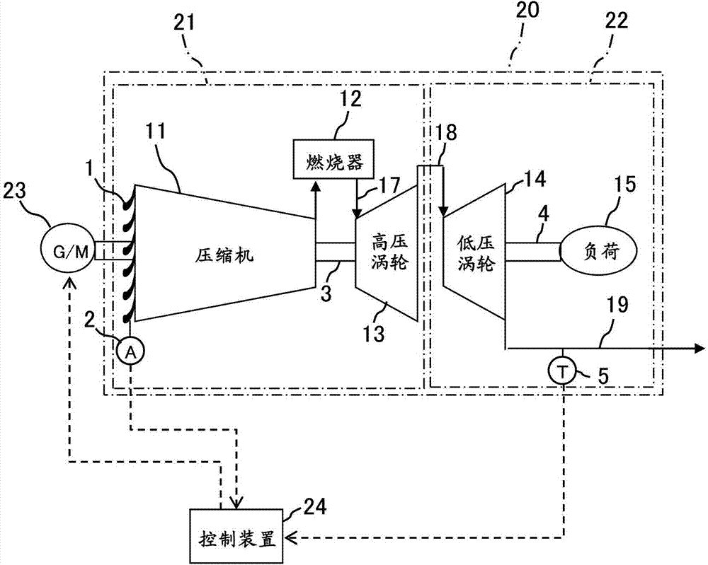
[0034] figure 1 It is a configuration diagram of the twin-shaft gas turbine according to the first embodiment of the present invention.

[0035] A twin-shaft gas turbine 20 shown in the figure includes a gas generator 21 , an output turbine 22 , a generator motor 23 , and a control device 24 .

[0036] (1) Gas generator

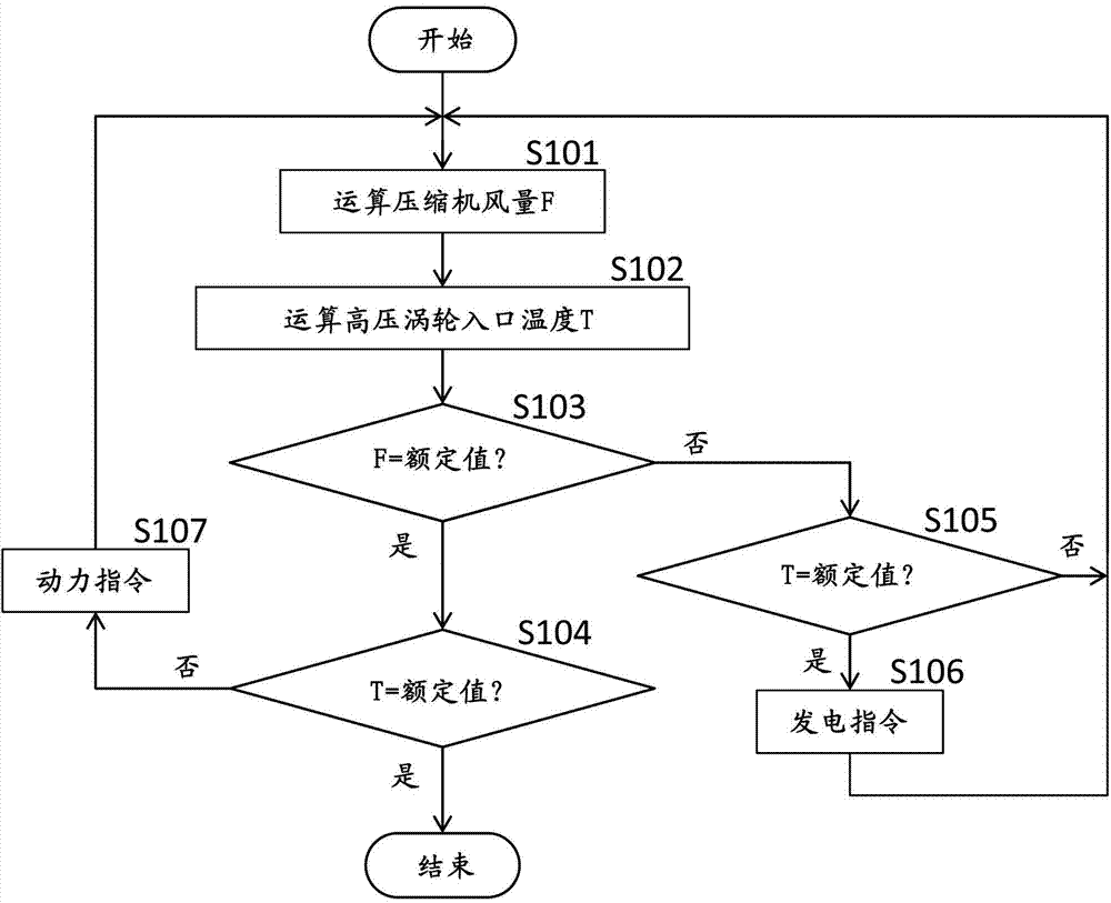
[0037] The gas generator 21 includes a compressor 11 , a combustor 12 , and a high-pressure turbine 13 as main elements. The compressor 11 compresses air taken in from the atmosphere to generate compressed air. An IGV (Inlet Guide Vane) 1 is provided at an inlet (air inlet) of the compressor 11 . The IGV1 is driven by an IGV driving device (not shown), and the air intake amount of the compressor 11 is changed by adjusting the opening degree of the IGV1. The angle detector 2 which detects the angle of the vane (opening degree of IGV1) is provided in IGV1. The combustor 12 mixes and combusts the compressed air from the c...

no. 2 approach

[0066] Figure 5 is a structural diagram of a twin-shaft gas turbine according to a second embodiment of the present invention, and is the same as figure 1 corresponding figure. In this figure, the same reference numerals as those in the preceding figures are assigned to the contents already explained, and description thereof will be omitted.

[0067] Such as Figure 4 As shown, the twin-shaft gas turbine 20A of this embodiment differs from the twin-shaft gas turbine 20 of the first embodiment in that a fuel compressor 25 is connected to the gas generator 21 as a load conditioner instead of the generator motor 23 . The fuel compressor 25 is a device that compresses fuel gas and supplies the compressed fuel gas 26 to the combustor 12 , and is connected to the compressor 11 via the gas generator shaft 3 . When the operating fluid of the compressor 11 reaches the rated flow rate (for example, when the IGV1 is fully opened or exceeds the set opening degree), the control device ...

no. 3 approach

[0070] Figure 6 is a structural diagram of a twin-shaft gas turbine according to a third embodiment of the present invention, and is the same as figure 1 corresponding figure. In this figure, the same reference numerals as those in the preceding figures are assigned to the contents already explained, and description thereof will be omitted.

[0071] Such as Figure 6 As shown, the difference between the twin-shaft gas turbine 20B of the present embodiment and the twin-shaft gas turbine 20 of the first embodiment is that, instead of the generator motor 23 , an extraction air flow control valve 27 is provided as a load regulator. The air extraction flow adjustment valve 27 is provided on the air extraction line 28 for extracting compressed air from the compressor 11 . The suction line 28 connects, for example, the intermediate section of the compressor 11 and the inlet of the low-pressure turbine 14 . In the present embodiment, when the air volume of the compressor 11 reach...


PUM


Abstract

A two-shaft gas turbine is provided that can raise an inlet temperature of a high-pressure turbine and the air quantity of a compressor to respective rated values at any atmospheric temperature without using a variable stator vane in the initial stage of a low-pressure turbine. The two-shaft gas turbine includes a power generator 21 having a compressor 11, a combustor 12 and a high-pressure turbine 13; a low-pressure turbine 14 driven by exhaust gas from the high-pressure turbine 13; a generator motor 23 connected to the gas generator 21; and a control unit 24. When either one of a value of the inlet temperature of the high-pressure turbine 13 and a value of the air quantity of the compressor 11 reaches a rated value before the other value reaches a rated value, the control unit 24 drives the generator motor 23 to bring the other value close to the rated value.

Description

technical field [0001] The invention relates to a twin-shaft gas turbine. Background technique [0002] Generally, a twin-shaft gas turbine includes a gas generator having a compressor, a combustor, and a high-pressure turbine, and a low-pressure turbine (power turbine) connected to a load device. The rotation shaft of the low-pressure turbine is separated from the rotation shaft of the gas generator (gas generator shaft). In the gas generator, the compressed air generated by the compressor is combusted together with fuel in the combustor, and the high-pressure turbine is driven by the combustion gas generated by the combustor to obtain the driving force of the compressor. The low-pressure turbine is driven by combustion gas after driving the high-pressure turbine, thereby driving a load device (see Patent Document 1). [0003] In general, in a twin-shaft gas turbine, the air volume passing through the compressor (the operating fluid flow rate of the compressor) or the inl...

Claims


Application Information

Patent Timeline
Patent Type & Authority Applications(China)
IPC IPC(8): F02C9/00F01D9/02
CPCF02C9/18F01D15/10F05D2270/313F05D2270/05F02C3/10F02C9/16F02C9/28
Inventor 七泷健治黑木英俊
Owner MITSUBISHI POWER LTD
Why Eureka
Try Eureka