Droplet injection device and nozzle recovery method for droplet injection device

A recovery method, droplet technology, applied in printing and other directions, can solve unsolved problems

Active Publication Date: 2014-12-24
KONICA MINOLTA INC
View PDF7 Cites 12 Cited by
  • Summary
  • Abstract
  • Description
  • Claims
  • Application Information

AI Technical Summary

Problems solved by technology

However, it prevents the clogging of the nozzle due to the thickening of the ink due to the evaporation of the liquid, but does not solve the problem due to the settling of solid particles contained in the ink

Method used


Image

  • Droplet injection device and nozzle recovery method for droplet injection device
  • Droplet injection device and nozzle recovery method for droplet injection device
  • Droplet injection device and nozzle recovery method for droplet injection device

Examples


Embodiment 1

[0183] Such as Figure 15 As shown, using a scanning type droplet ejection device in which ink receiving parts are respectively arranged in the non-printing areas on both sides of the recording medium, from a UV liquid that uses titanium oxide containing a dispersant and a solid particle whose specific gravity is larger than that of the dispersant Ink (the specific gravity difference between the dispersant and solid particles: 0.25, the content of the substance whose vapor pressure is greater than water at room temperature: 5%), performs specified printing in the printing area of ​​the recording medium, and the nozzle is in the main scanning direction. Since the end portion is folded back, every time it reaches a non-printing area, after applying a micro-vibration pulse at a frequency half of the droplet ejection frequency during printing, the ink receiving portion ejects droplets at the same frequency as the ejection frequency.

[0184] As a result, no nozzle clogging occurs ...

Embodiment 2

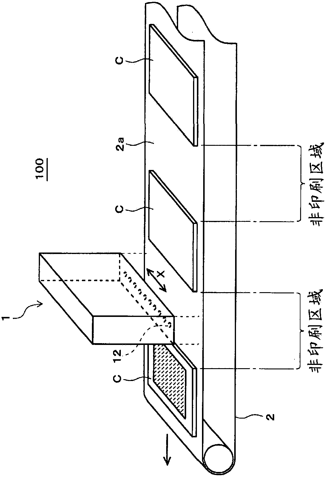
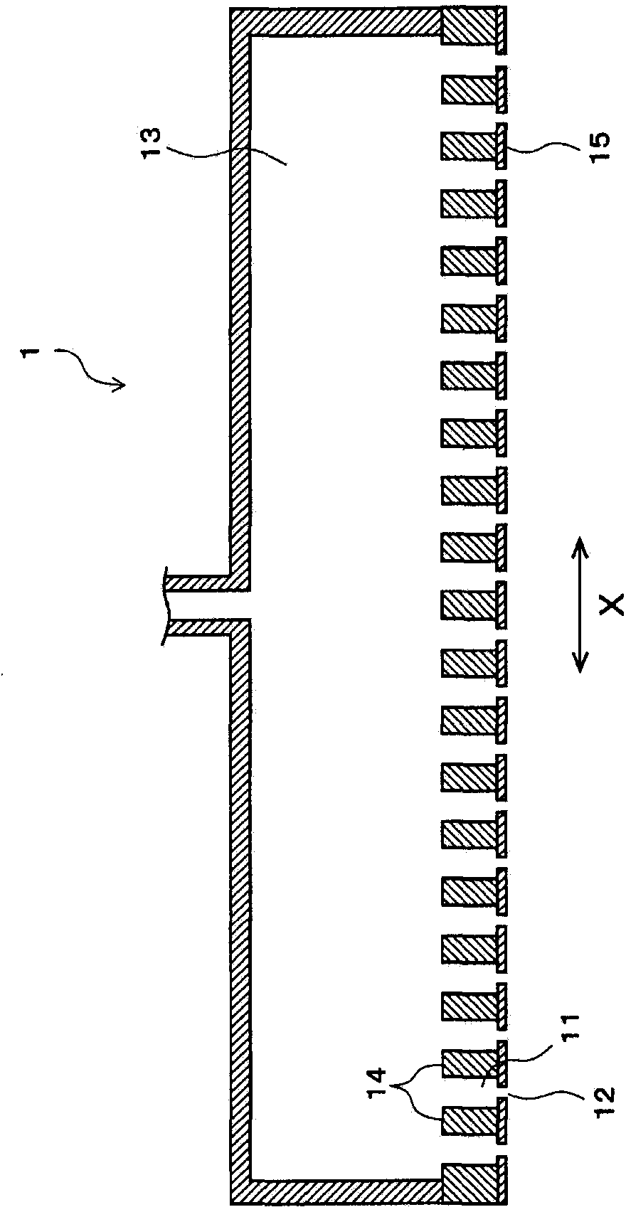
[0192] Such as figure 1 As shown, using a line-type droplet ejection device that prints on the surface of ceramic tiles conveyed by a conveyor belt through a single channel from the nozzle, from ink using a dispersant and yellow pigment particles as solid particles (The specific gravity difference between the dispersant and the solid particles: 0.30, the content of the substance whose vapor pressure is greater than water at room temperature: 3%), the specified printing was performed in the printing area on the surface of the ceramic tile. The ink used for ceramic tiles has a high density, and the pigment particles are easy to settle, so whenever the nozzle comes to the non-printing area between the ceramic tiles, after applying a micro-vibration pulse with the same frequency as the droplet ejection frequency during printing, Droplet discharge at the same frequency as the discharge frequency was performed in the ink receiving unit.

[0193] As a result, no nozzle clogging occu...


PUM


Abstract

The present invention aims to efficiently eliminate settling of solid particles in the ink, and enable long-term stable droplet injection. Specifically, a droplet injection device comprises an ink chamber, a nozzle corresponding to the ink chamber, an energy imparting unit, and a drive pulse generation unit. The energy imparting unit is impacted and driven by a drive pulse to impart energy to the ink in the ink chamber. The nozzle allows droplets to be sent out from the nozzle, so that a printing area for recording material is printed. The drive pulse generation unit generates a shoot-out pulse allowing a droplet to be sent out from the nozzle, and provides a micro vibration pulse as a drive pulse for the ink in the ink chamber based on a degree that the droplet is not sent out from the nozzle. The ink comprises dispersant, and solid particles with a proportion greater than the dispersant. An updating unit is also provided. The updating unit applies micro vibration motion of a plurality of micro vibration pulses and then a plurality of shoot-out pulses, so as to enable split motion with the same.

Description

technical field [0001] The present invention relates to a liquid droplet ejection device and a nozzle recovery method of the liquid droplet ejection device, and in particular to a liquid droplet ejection device and a liquid droplet ejection device capable of suppressing the settling of solid particles contained in ink to perform long-term stable droplet ejection Nozzle recovery method for the device. Background technique [0002] A droplet ejection device that performs printing by ejecting liquid droplets from a head is generally used as an inkjet printer in various industrial applications. The application of this industrial inkjet has been increasing year by year, and in recent years, it has been used not only for printing on paper, textiles, plastic boards, etc., but also for printing patterns on the surface of ceramic tiles. Along with this, performance capable of stably ejecting various inks for a long period of time is required for a droplet ejection device. [0003] ...

Claims


Application Information

Patent Timeline
Patent Type & Authority Applications(China)
IPC IPC(8): B41J2/165
Inventor 小林谅平
Owner KONICA MINOLTA INC
Why Eureka
Try Eureka