Internal power pneumatic automatically-intermittent circulator

A pneumatic, internal power technology, applied in the direction of gas production bioreactors, biochemical instruments, biochemical equipment and methods, etc., can solve the problems of long production cycle, high production energy consumption, poor comprehensive benefits, etc., to reduce power The effect of consumption, shortening production cycle and improving production efficiency

Inactive Publication Date: 2014-12-24
方义 +1
View PDF5 Cites 4 Cited by
  • Summary
  • Abstract
  • Description
  • Claims
  • Application Information

AI Technical Summary

Problems solved by technology

Disadvantages of no external power cycle and agitated digester: the digester is bulky, high infrastructure investment, large area, long production cycle, low efficiency, and the disadvantage of IC internal power cycle digester: not suitable for high suspended solids content The material liquid is not conducive to heat preservation, not suitable for small enterprises
Disadvantages of external power cycle stirring digester: large investment in motors and water pumps, high production electricity and maintenance costs, and poor comprehensive benefits
Taking the most efficient fluidized bed and expanded bed as an example, because the motor drives the water pump to circulate the material and liquid during the production process, the production energy consumption is too high to be used in actual production

Method used


Image

  • Internal power pneumatic automatically-intermittent circulator

Examples


Embodiment Construction

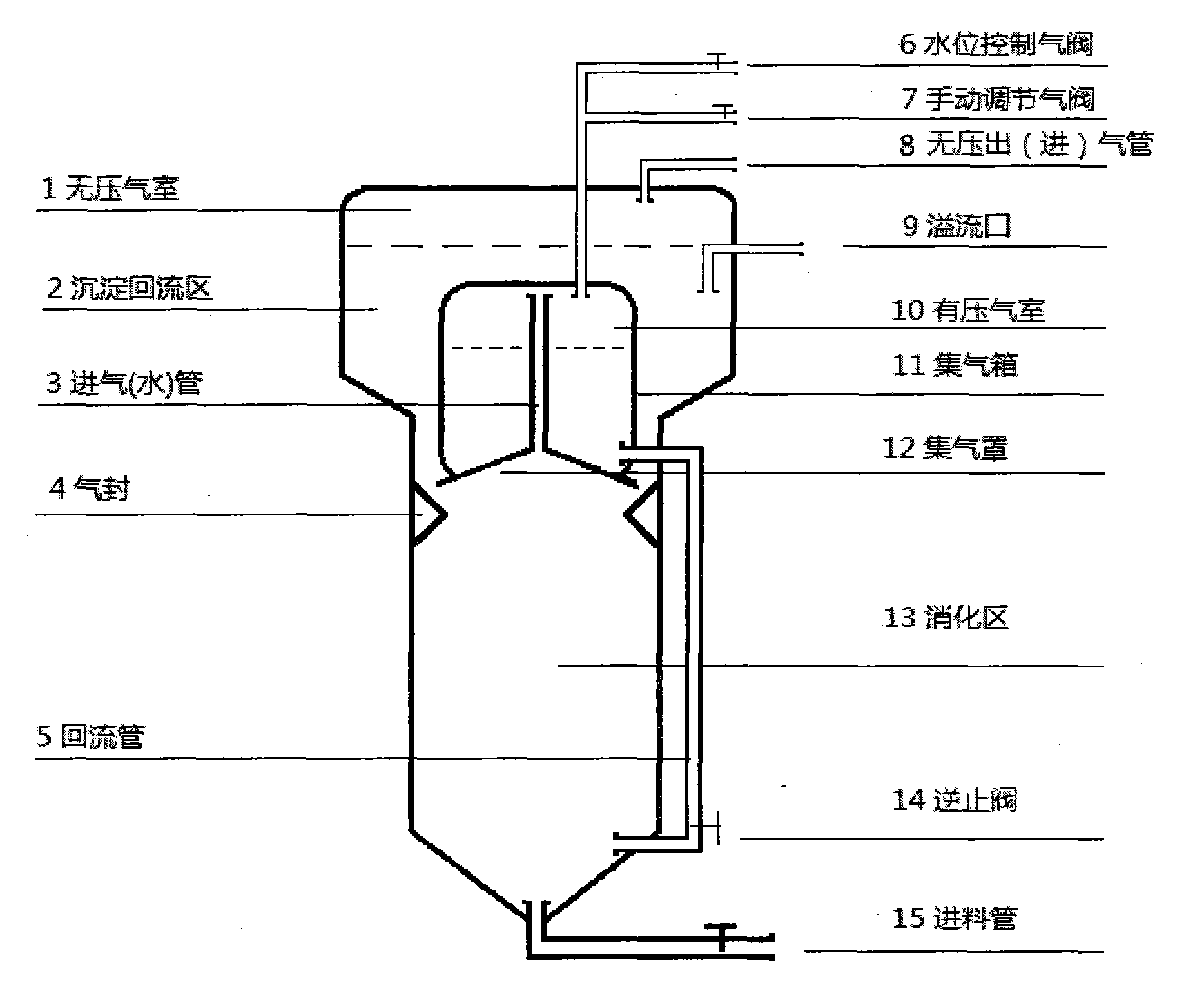
[0007] In the figure, the digestion zone 13 continuously produces biogas, and the biogas enters the gas collection box 11 continuously through the gas seal 4 and the gas collection hood 11 through the intake (water) pipe 3. At this time, the water level control gas installed on the top of the gas collection box 11 The valve 6 is in the closed state, and the pressure in the gas collection box 11 is constantly increasing to force the feed liquid to be continuously pressed into the bottom of the digestion zone 13 by the gas through the return pipe 5 and the check valve 14 installed at the bottom of the gas collection box 11. When the water level in the gas box 11 is pressed to the set low water level by the gas, the water level control valve 6 is automatically opened, and the gas in the gas collection box 11 is continuously discharged, because the water level in the sediment return area 2 is higher than that of the gas collection box 11 Yes, at this time, the feed liquid in the up...


PUM


Abstract

The invention discloses a device which achieves pneumatic automatically-intermittent circulation by adopting gas generated in an anaerobic digester as internal power. The device is characterized in that a circulation loop is formed by feeding a gas collecting tank 11, a water level control gas valve 6, a gas collecting hood 12, a gas (water) inlet pipe 3, a reflux pipe 5 and a check valve 14 to the bottom of a digestion area 13 together. When the water level control gas valve 6 is closed, biogas continuously enters the gas collecting tank 11 by virtue of a gas seal 4, the gas collecting hood 12 and the gas (water) inlet pipe 3 to ensure that pressure in the gas collecting tank 11 is continuously increased, and a material liquid in the gas collecting tank 11 is forced to enter the bottom of the digestion area 13 by virtue of the reflux pipe 5 and the check valve 14. When the water level of the gas collecting tank 11 is lowered to the set water level, the water level control gas valve 6 is automatically opened, and the gas in the gas collecting tank is continuously exhausted; when the water level in the gas collecting tank 11 reaches the set low water level, the water level control gas valve 6 is automatically opened, the pressure in the gas collecting tank 11 is reduced, water in the upper part of the digestion area is absorbed into the gas collecting tank by virtue of the gas (water) inlet pipe 3, and when the water level in the gas collecting tank 11 reaches the set high water level, the water level control gas valve 6 is automatically closed. The gas collecting tank enters the next round of water discharge, gas exhaust and water absorption circulation so as to achieve internal power automatically-intermittent circulation.

Description

Technical field [0001] The invention relates to a device for generating flammable gas through anaerobic digestion of organic matter under anaerobic conditions, and providing an internal dynamic pneumatic automatic intermittent cycle for anaerobic digesters. Background technique [0002] At present, anaerobic digesters are used in many aspects such as bioenergy production, municipal garbage, sewage treatment, and aquaculture manure treatment. Proper circulation and stirring of the feed liquid during the anaerobic digestion process is an effective way to improve the performance of the anaerobic digester. Existing digesters can be divided into two types with external power circulation and agitation and without external power circulation and agitation in terms of circulation and agitation. Disadvantages of no external power cycle and agitated digester: the digester is bulky, high infrastructure investment, large area, long production cycle, low efficiency, and the disadvantage ...

Claims


Application Information

Patent Timeline
Patent Type & Authority Applications(China)
IPC IPC(8): C12M1/107
CPCC12M21/04C12M23/36C12M29/18C12M41/44
Inventor 方义方慧敏
Owner 方义
Why Eureka
Try Eureka