Autonomous all-weather stellar refraction satellite location method

A starlight refraction and autonomous positioning technology, applied in the field of astronomical navigation, can solve the problems of high technical difficulty, low precision, and many instruments and equipment, and achieve the effect of improving navigation accuracy and high data update rate

Active Publication Date: 2014-12-24
CHINA ACADEMY OF SPACE TECHNOLOGY
View PDF6 Cites 6 Cited by
  • Summary
  • Abstract
  • Description
  • Claims
  • Application Information

AI Technical Summary

Problems solved by technology
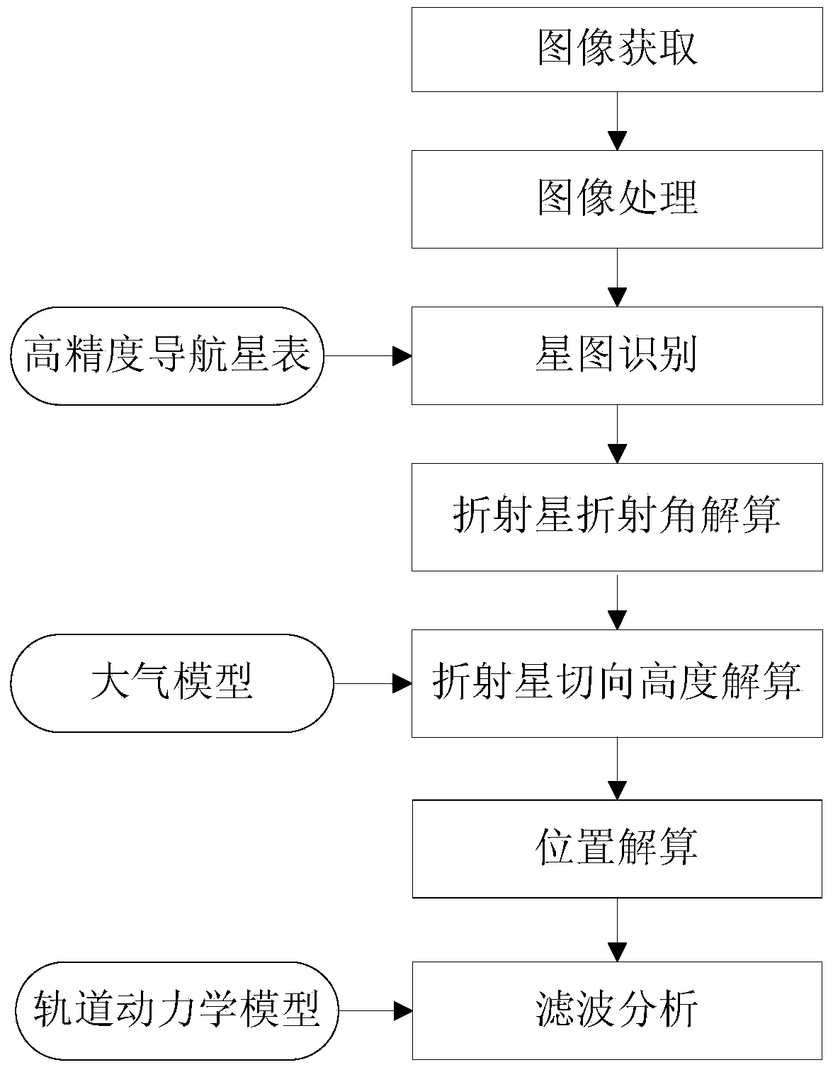
Since the concept of starlight refraction navigation was proposed in 1982, it has attracted the attention of many scholars and achieved certain research results. However, Robert, Robert and Eliezer (Guidance and Control Conference, Gatlinburg, TN, August 15-17, 1983: 359- 367), Whilte, Thurman and Barnes (Proceedings of the Forty-First Annual Meeting, the Institute of Navigation, Annapolis, MD, June 25-27, 1985:83-89), Lair and Duchon (Acta Astronautica, 1988, 17( 10): 1069-1079), Ning and Fang (Aerospace Science and Technology 11(2007): 222-228) and other major researchers discussed more about the principle of starlight refraction navigation position calculation and method, because the earth's illumination conditions will seriously affect the navigation accuracy of starlight refraction, and even directly cause the starlight refraction navigation system to fail to obtain positioning results, so the previous method fails to meet the requirements of satellite autonomous positioning for all-day and high precision
[0003] Chinese Patent Publication No. CN 103616028A, dated March 5, 2014, titled "A Method for Autonomous Navigation of Starlight Refraction S

Method used


Image

  • Autonomous all-weather stellar refraction satellite location method
  • Autonomous all-weather stellar refraction satellite location method
  • Autonomous all-weather stellar refraction satellite location method

Examples


Embodiment 1

[0095] The present invention is based on the image processing technology for star extraction under the strong background introduced above, and verifies the feasibility of star extraction under the strong background of the earth through ground-based observation of the moon and its surrounding stars. Exposure, 12th magnitude stars are identifiable near the edge of the moon. According to the differences and similarities between space-based observations and ground-based observations, and for different observation background brightness and observation equipment, based on the following detection system signal-to-noise ratio formula, it can be deduced that the starlight refraction sensor can achieve 7.5 Detection of stellar magnitudes.

[0096] s / N = ψ s ( Aq s 2 t ) ...

Embodiment 2

[0099] The satellite starlight refraction navigation simulation system is under the condition that the star measurement accuracy is 3" (3σ) and the atmospheric model error is 1%, by simulating the starlight refraction navigation function in the process of satellite GTO (20000km ~ 36000km), the starlight refraction navigation system is obtained The positioning accuracy is better than 1.2km.


PUM


Abstract

The invention relates to an autonomous all-weather stellar refraction satellite location method. The method comprises the following steps: observing and acquiring a star map by adopting a CCD (charge coupled device) with a saturation inhibition function, performing the image processing on the acquired star map, and extracting a non-refracted star and a refracted star; matching the star map with a star map of a navigation star catalogue by utilizing a triangular matching algorithm to acquire the right ascension and declination of each star on the star map; searching the star map for a fixed star which is closest to each refracted star to be used as a corresponding star of the refracted star, and calculating a refraction angle gamma of each refracted star; calculating the tangential height h of each refracted star according to an atmosphere model and the refraction angle; and selecting three refracted stars on the observation star map, and calculating the position of a satellite under earth centered inertial system according to the right ascensions, declinations and tangential heights h of the three refracted star. By adopting the method, the all-weather high-precision astronomical autonomous navigation of the satellite is realized; moreover, the data updating rate is high, and the involved equipment is simple, low in cost and low in power consumption.

Description

technical field [0001] The invention belongs to the field of celestial navigation, and relates to an all-time self-positioning method for starlight refraction satellites, and is especially suitable for satellites with all-time and high-precision self-navigation requirements. Background technique [0002] Starlight refraction astronomical navigation is a method of using optical sensors to measure the refraction of starlight when it passes through the atmosphere at the edge of the earth, indirectly obtain horizon information, obtain the position of the satellite in the geocentric coordinate system, and determine the orbit of the satellite. Since the concept of starlight refraction navigation was proposed in 1982, it has attracted the attention of many scholars and achieved certain research results. However, Robert, Robert and Eliezer (Guidance and Control Conference, Gatlinburg, TN, August 15-17, 1983: 359- 367), Whilte, Thurman and Barnes (Proceedings of the Forty-First Annua...

Claims


Application Information

Patent Timeline
IPC IPC(8): G01C21/24
CPCG01C21/24
Inventor 林亲李志李怀锋姜晓军王汇娟卢晓猛
Owner CHINA ACADEMY OF SPACE TECHNOLOGY
Why Eureka
Try Eureka