Manufacturing method of current collector of lead-acid storage battery

A technology of lead-acid battery and manufacturing method, which is applied in the direction of battery electrodes, electrode carriers/collectors, circuits, etc., which can solve problems such as large power consumption, poor fluidity of lead liquid, surface defects, etc., and achieve power saving and weight reduction , complex shape effects

Active Publication Date: 2014-12-24
ZHEJIANG NARADA POWER SOURCE CO LTD +1
View PDF7 Cites 4 Cited by
  • Summary
  • Abstract
  • Description
  • Claims
  • Application Information

AI Technical Summary

Problems solved by technology

[0003] There are many disadvantages in the traditional process, 1: If a large amount of electric energy needs to be used to heat the lead melting pot and the liquid pumping equipment, a large amount of electric energy will be consumed; 2: Since the lead liquid will cool in the mold, the fluidity of the lead liquid will become poor and cannot flow Into a thinner and narrower mold, so the rib design of the traditional current collector is thicker, the weight is large, and the specific surface area is small
The contact distance with the lead paste is large, the charging is slow, the high current performance is poor, and the utilization rate of the lead paste is low; 3: Since the flow of the current collector in the mold depends entirely on the fluidity of the liquid lead and the gravity of the lead flowing to each part of the mold A space is prone to defects such as broken ribs, holes, surface defects, and insufficient compactness; 4: There will be some lead on the upper end of the current collector mold in the traditional process. After demoulding, the excess part needs to be cut and then returned to the lead melting pot to increase Process steps, waste of electrical energy
5: The production process of traditional crafts will pollute the environment with a large amount of lead dust and lead fume, and it is necessary to increase the investment in environmental protection equipment
The lead melting pot radiates a lot of heat energy, and the working environment is poor

Method used

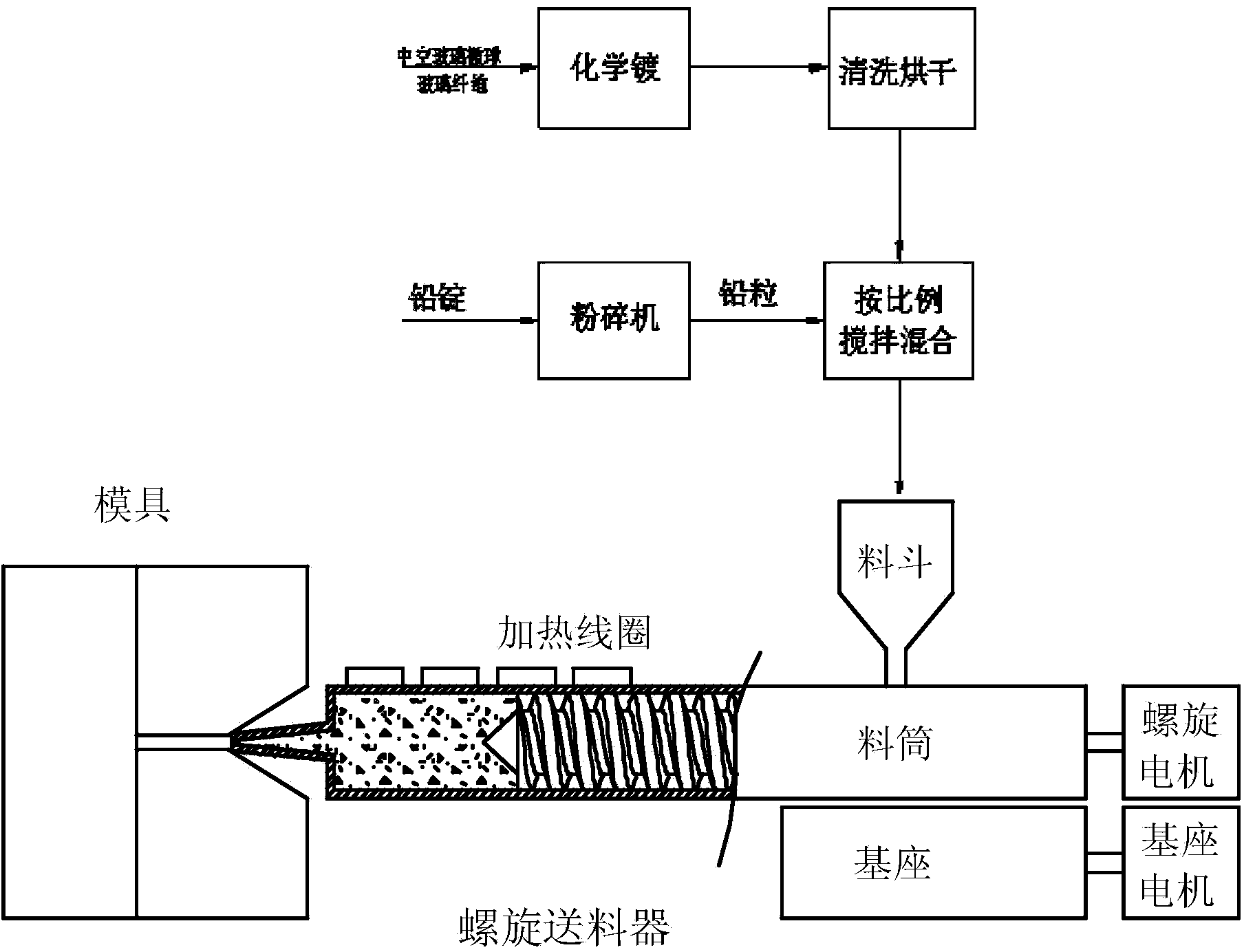
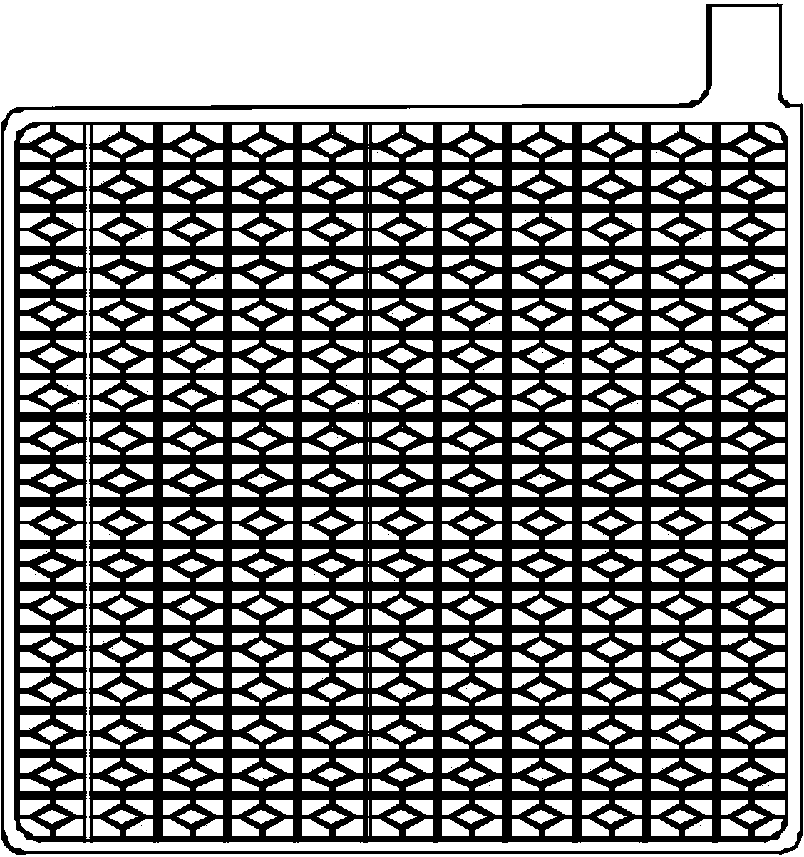
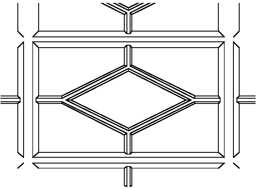

Image

  • Manufacturing method of current collector of lead-acid storage battery
  • Manufacturing method of current collector of lead-acid storage battery
  • Manufacturing method of current collector of lead-acid storage battery

Examples


Embodiment Construction

[0021] The manufacturing method of the lead-acid battery current collector provided by the present invention, the material components of the current collector include lead or lead-containing alloy, and also include: low-density blended material particles, reinforcing fibers;

[0022] The low-density blended material particles are made of hollow glass with a particle size of 10-150 microns, and the microspheres are pretreated with chemical tin, silver or gold; the reinforcing fibers are made of glass with a diameter of 10-100 microns. Fibers, also pretreated with electroless tin, silver or gold;

[0023] Pretreat lead or lead-containing alloys into small balls or cylinders with a diameter of about 5-20mm, and the height of the cylinders is also about 5-20mm, and mix them evenly with low-density blending material particles and reinforcing fibers;

[0024] Provide a mold for extrusion molding of current collectors, heat the homogeneously mixed lead or lead-containing alloys, low-...


PUM

PropertyMeasurementUnit
densityaaaaaaaaaa
diameteraaaaaaaaaa
densityaaaaaaaaaa

Abstract

The invention provides a manufacturing method of a current collector of a lead-acid storage battery. The manufacturing method comprises the following steps: preprocessing a lead or leaded alloy into particles and uniformly mixing the particles and low-density blended material particles as well as reinforced fibers; heating the uniformly mixed lead or leaded alloy, low-density blended material particles and reinforced fibers to a temperature interval of higher than a melting point of the lead or leaded alloy and lower than melting points of the low-density blended material particles and the reinforced fibers, extruding the mixture into a die to carry out forming processing to form the current collector of the lead-acid storage battery. The current collector manufactured by the technical scheme adopted by the invention has the lowest density of 3g/cm<3>; the largest weight of the current collector can be reduced by 70 percent to the greatest extent; compared with the surface area of a current collector manufactured by a conventional process, the surface area can be increased by 40 percent to the greatest extent; the intensity of the current collector is improved by 200 percent; the current collector manufactured by the manufacturing method can be widely applied to the lead-acid storage battery and is particularly applied to a high-energy-density, high-power and quick-charge start-stop battery.

Description

technical field [0001] The invention relates to a method for manufacturing a current collector of a lead-acid storage battery, and is especially suitable for the production and manufacture of an ultra-thin current collector. Background technique [0002] The traditional lead-acid battery current collector adopts the production process of gravity casting. Because the process requires that the lead ingot be heated and melted in a lead melting pot, the liquid lead is poured into the mold through the pumping equipment, and the molten lead automatically flows into each gap of the mold, and becomes a fluid after cooling. [0003] There are many disadvantages in the traditional process, 1: If a large amount of electric energy needs to be used to heat the lead melting pot and the liquid pumping equipment, a large amount of electric energy will be consumed; 2: Since the lead liquid will cool in the mold, the fluidity of the lead liquid will become poor and cannot flow Into a thinner...

Claims


Application Information

Patent Timeline
Patent Type & Authority Applications(China)
IPC IPC(8): H01M4/82
CPCH01M4/666H01M4/68H01M4/82Y02E60/10
Inventor 刘桃松党志敏黄德金
Owner ZHEJIANG NARADA POWER SOURCE CO LTD
Why Eureka
Try Eureka