Supercharge Your Innovation With Domain-Expert AI Agents!

Non-switching loss type full-bridge non-isolated photovoltaic grid-connected inverter and switching control sequence

A non-isolated, non-switching technology, used in photovoltaic power generation, AC power input to DC power output, output power conversion devices, etc. It can eliminate the leakage current and reverse recovery problems

Active Publication Date: 2016-11-09
SOUTHEAST UNIV
View PDF4 Cites 0 Cited by
  • Summary
  • Abstract
  • Description
  • Claims
  • Application Information

AI Technical Summary

Problems solved by technology

The existing technology proposes a non-isolated grid-connected inverter soft switching solution for this defect, but there is a problem in the prior art that the resonant capacitor voltage cannot be reliably clamped at a fixed voltage value, so that the peak value of the resonant inductor current in the resonant circuit may be low In the case of high-frequency main switch conduction current, it loses the opportunity of zero current shutdown
[0005] In addition, the turn-on process of the high-frequency main switch is still a hard switch, the turn-off process of the high-frequency auxiliary switch is also a hard switch, and the diode of the low-frequency reversing switch unit still has a reverse recovery problem

Method used


Image

  • Non-switching loss type full-bridge non-isolated photovoltaic grid-connected inverter and switching control sequence
  • Non-switching loss type full-bridge non-isolated photovoltaic grid-connected inverter and switching control sequence
  • Non-switching loss type full-bridge non-isolated photovoltaic grid-connected inverter and switching control sequence

Examples


Embodiment 1

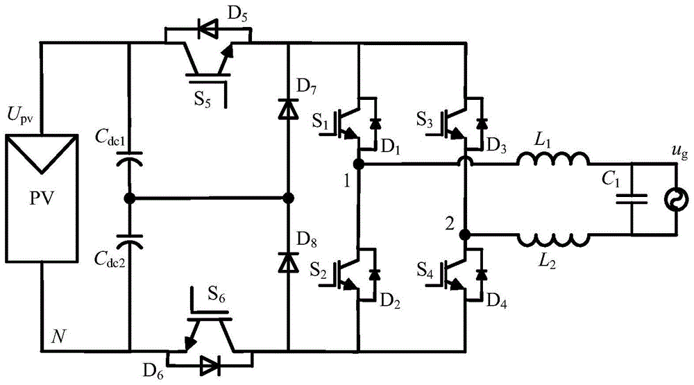
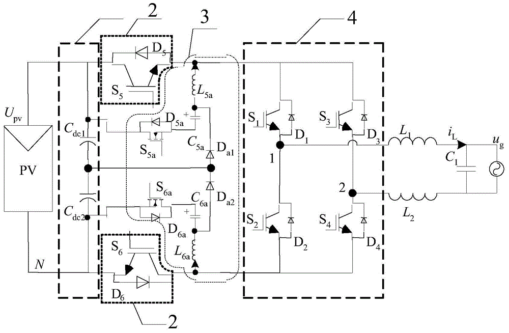
[0034] Such as figure 2 As shown, the configuration of the main circuit in Embodiment 1 of the present invention consists of the first voltage dividing capacitor C dc1 and the second divider capacitor C dc2 Form the basic unit 1;

[0035] By the fifth power switch tube S 5 and the fifth power diode D 5 Parallel combination, the sixth power switch tube S 6 and the sixth power diode D 6 Parallel combination forms the basic unit 2;

[0036] By the fifth auxiliary power switch S 5a and the fifth auxiliary power diode D 5a Parallel combination, the fifth auxiliary resonant inductor L 5a , the fifth auxiliary resonant capacitor C 5a , the sixth auxiliary power switch tube S 6a and the sixth auxiliary power diode D 6a Parallel combination, the sixth auxiliary resonant inductor L 6a , the sixth auxiliary resonant capacitor C 6a and the first auxiliary freewheeling clamp power diode D a1 , The second auxiliary freewheeling clamp power diode D a2 Form the basic unit 3; ...

Embodiment 2

[0044] Such as Figure 7 As shown, the main circuit of the second embodiment of the present invention consists of a DC filter capacitor C dc Composing the basic unit 71;

[0045] By the fifth power switch tube S 5 and the fifth power diode D 5 Parallel combination, the sixth power switch tube S 6 and the sixth power diode D 6 Parallel combination forms the basic unit 72;

[0046] By the fifth auxiliary power switch S 5a and the fifth auxiliary power diode D 5a Parallel combination, the fifth auxiliary resonant inductor L 5a , the fifth auxiliary resonant capacitor C 5a , the sixth auxiliary power switch tube S 6a and the sixth auxiliary power diode D 6a Parallel combination, the sixth auxiliary resonant inductor L 6a , the sixth auxiliary resonant capacitor C 6a and the first auxiliary freewheeling power diode D a1 Composing the basic unit 73;

[0047] By the first power switch tube S 1 and the first power diode D 1 Parallel combination, the second power switch...

Embodiment 3

[0051] Such as Figure 8 As shown, the main circuit of the third embodiment of the present invention consists of the first voltage dividing capacitor C dc1 and the second divider capacitor C dc2 Composing the basic unit 81;

[0052] By the fifth power switch tube S 5 and the fifth power diode D 5 Parallel combination, the sixth power switch tube S 6 and the sixth power diode D 6 Parallel combination forms basic unit 82;

[0053] By the fifth auxiliary power switch S 5a and the fifth auxiliary power diode D 5a Parallel combination, the fifth auxiliary resonant inductor L 5a , the fifth auxiliary resonant capacitor C 5a , the sixth auxiliary power switch tube S 6a and the sixth auxiliary power diode D 6a Parallel combination, the sixth auxiliary resonant inductor L 6a , the sixth auxiliary resonant capacitor C 6a and the first auxiliary freewheeling power diode D a1 Composing the basic unit 83;

[0054] clamped by the seventh power diode D 7 and the eighth clampi...


PUM


Abstract

The invention discloses a non-isolated photovoltaic grid-connected inverter without switching loss and a switch control sequence, wherein the inverter includes a voltage dividing capacitor branch, a high-frequency main switch unit, a resonant network and a low-frequency commutation switch unit. By adding two sets of resonant networks composed of fully-controlled switches, resonant capacitors and resonant inductors, and auxiliary freewheeling clamp diodes to form a zero-current conversion branch, and with the above-mentioned switch control sequence, the fifth power switch tube S can be realized. 5 and the sixth power switch S 6 The zero-current turn-on and zero-current turn-off conditions of the fifth auxiliary switch tube S a5 and the sixth auxiliary switch S a6 zero-current turn-on and zero-current turn-off conditions, and eliminates low-frequency commutation switch cell diode D 1 ~D 4 reverse recovery and other issues, and ensure that the common-mode voltage of the inverter is always at half of the battery voltage during power transmission, resonance phase and freewheeling phase to eliminate leakage current, so that a non-isolated grid-connected inverter can be realized high frequency and miniaturization.

Description

technical field [0001] The invention relates to the technical field of high-efficiency grid-connected inverter topology, in particular to a full-bridge non-isolated photovoltaic grid-connected inverter without switching loss. Background technique [0002] The non-isolated photovoltaic grid-connected inverter has a simple circuit structure and high conversion efficiency and has been widely used in the industry. Such as figure 1 As shown, the existing technologies all work in the hard switching mode, and the ideal efficiency can only be achieved by operating at a relatively low switching frequency (10-20kHz), and relatively large filter inductors and filter capacitors are required, which increases and The volume weight of the grid inverter increases the cost. [0003] After research, it is found that the main factor limiting the increase of switching frequency of non-isolated grid-connected inverters is the switching loss of high-frequency switches. With the increase of swit...

Claims


Application Information

Patent Timeline
Patent Type & Authority Patents(China)
IPC IPC(8): H02M7/5387
CPCY02E10/56
Inventor 肖华锋
Owner SOUTHEAST UNIV
Features
  • R&D
  • Intellectual Property
  • Life Sciences
  • Materials
  • Tech Scout
  • Unparalleled Data Quality
  • Higher Quality Content
  • 60% Fewer Hallucinations
Learn More