Supercharge Your Innovation With Domain-Expert AI Agents!

Device and Control Method for Slow Cooling Section of Radiation Cooling System of Horizontal Annealing Furnace

A technology of radiation cooling and control method, which is applied in the field of metallurgical heat treatment and annealing, can solve the problems of easily moving atmosphere, increased investment in equipment structure, unfavorable maintenance and overhaul, etc., and achieves the effect of stable cooling rate, simple control method, uniform and slow cooling

Active Publication Date: 2016-12-28
BAOSHAN IRON & STEEL CO LTD
View PDF4 Cites 0 Cited by
  • Summary
  • Abstract
  • Description
  • Claims
  • Application Information

AI Technical Summary

Problems solved by technology

[0004] 1) The cooling bellows are arranged on the upper and lower surfaces of the strip, and the method of purging cooling is not conducive to the uniformity of the strip during cooling, and it is also not conducive to improving the shape of the strip.
[0005] 2) The cooling method of directly purging the surface of the strip is not conducive to the relative stability of the furnace pressure of the annealing furnace. If the cooling air volume is dynamically adjusted, the atmosphere between the various sections in the furnace is easy to move in series and cannot reach the annealing furnace. Stable control of the atmosphere in each section
[0006] 3) To use air box cooling, it is necessary to configure related equipment for each air box. Each air box must be equipped with a circulating fan and a heat exchanger, which increases the investment in equipment construction and is also necessary for future maintenance and repair. very unfavorable
[0011] However, this patent is mainly used for dehumidification and prevention of condensation in factory buildings, and its structure and usage methods are not related to this topic

Method used


Image

  • Device and Control Method for Slow Cooling Section of Radiation Cooling System of Horizontal Annealing Furnace
  • Device and Control Method for Slow Cooling Section of Radiation Cooling System of Horizontal Annealing Furnace
  • Device and Control Method for Slow Cooling Section of Radiation Cooling System of Horizontal Annealing Furnace

Examples


Embodiment 1

[0069] Implementation control method of the present invention is:

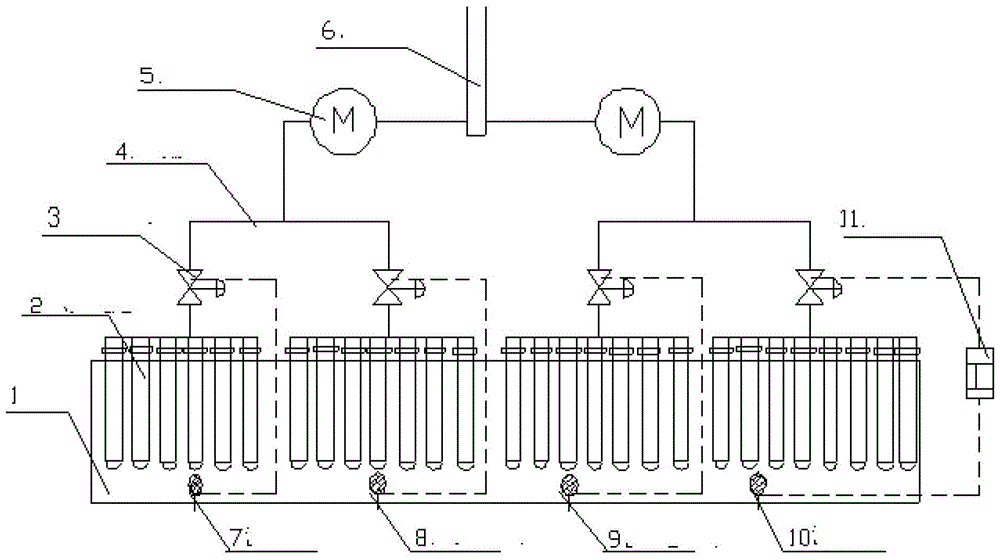
[0070] The entire slow cooling section can be divided into 4-8 sections, each section (or two sections) can be equipped with an exhaust fan, and fans with different power can be configured according to actual needs.

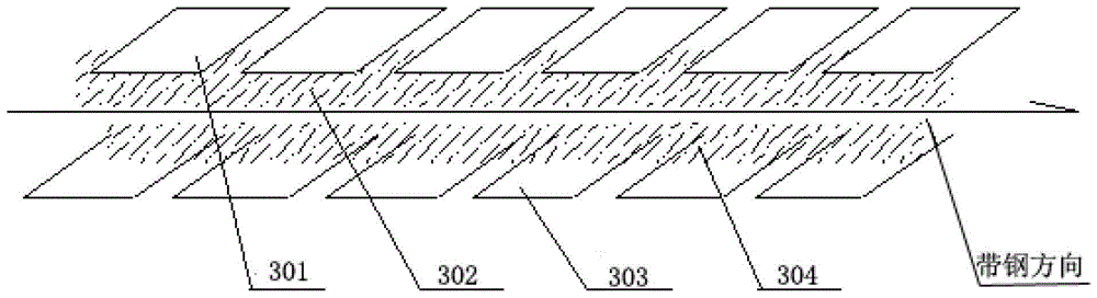
[0071] According to the cooling requirements, a certain number of radiation cooling jackets are arranged in each section, and the radiation cooling pipes are arranged crosswise on the upper and lower surfaces of the strip.

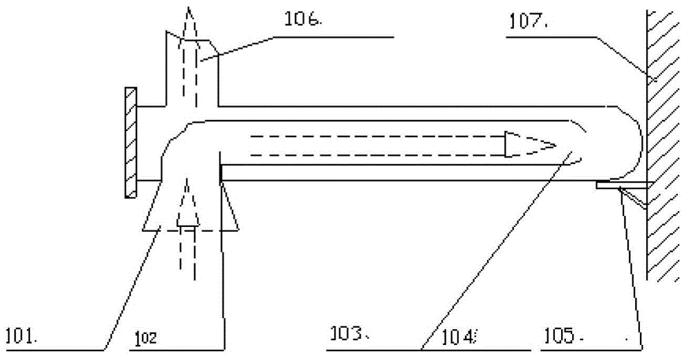
[0072] The distance between the upper and lower cooling radiant sleeves and the steel strip is controlled at 50mm--150mm.

[0073] A temperature detector is installed in each section, a flow regulating valve is installed on the air discharge pipe, and the air flow of the radiant tube is adjusted through the information feedback controller, so as to achieve the purpose of adjusting the temperature in the furnace.

[0074] The layout of the radiant tubes in the furnace is as f...


PUM


Abstract

An annealing furnace radiation cooling system slow cooling section device and its control method, the slow cooling section device is set to 4-8 sections, each section is respectively equipped with an air flow control valve (3) and a temperature detector , when the temperature detector detects the temperature in the furnace, the information is passed through the feedback controller (11) to adjust the air flow regulating valve; each section is arranged with radiation sleeves (2) crossed above and below the strip, through the radiation sleeve The cold air in the pipe radiates to cool the steel strip, and the flow regulating valve (3) connected to each section is connected to the exhaust fan (5) through the air pipe (4) and then discharged from the exhaust chimney (6). According to the present invention, the production process of the slow cooling section can be set according to the original target temperature. According to the actual temperature in the furnace, the gas flow in the radiation cooling pipe is automatically adjusted according to the furnace temperature requirement, and the control method is relatively simple. , strong operability and easy daily maintenance.

Description

technical field [0001] The invention relates to the field of metallurgical heat treatment annealing, in particular to a slow cooling section device of a radiation cooling system of a horizontal annealing furnace and a control method thereof in a continuous annealing production line of a cold rolling continuous unit annealing requiring slow cooling. Background technique [0002] In the heat treatment annealing process, there are generally production processes such as heating section, soaking section, slow cooling section, fast cooling section and air cooling section; the thermal drawing annealing unit of the first phase of the silicon steel department of a steel company also uses the same the above process. During the annealing process of the product, the slow cooling section plays a vital role, and the slow cooling speed has a great influence on the shape of the strip surface. The cooling method used in the slow cooling section of the first-stage thermal drawing annealing u...

Claims


Application Information

Patent Timeline
Patent Type & Authority Patents(China)
IPC IPC(8): C21D1/26
Inventor 卢纪平余伟郭万青章培莉
Owner BAOSHAN IRON & STEEL CO LTD
Features
  • R&D
  • Intellectual Property
  • Life Sciences
  • Materials
  • Tech Scout
  • Unparalleled Data Quality
  • Higher Quality Content
  • 60% Fewer Hallucinations
Learn More