
Crude oil gathering and transportation heating furnace tail gas waste heat recycle and emission reduction device

A waste heat recovery and heating furnace technology, which is applied in heat storage heaters, fluid heaters, lighting and heating equipment, etc., can solve the problems that restrict energy saving and emission reduction of crude oil gathering and transportation joint stations, environmental pollution, waste of latent heat of water vapor, etc.

Inactive Publication Date: 2014-12-31
中能纪(北京)国际科技有限公司
View PDF5 Cites 3 Cited by
  • Summary
  • Abstract
  • Description
  • Claims
  • Application Information

AI Technical Summary

Problems solved by technology

[0002] At present, one or more heating furnaces using natural gas as fuel are generally used in my country's crude oil gathering and transportation joint stations to complete the crude oil preheating work in the process of crude oil gathering and transportation. For main equipment with a water temperature of 80-90°C, the crude oil is preheated by circulating water through preheating of the crude oil and heat tracing of the external pipeline; , the volume composition of water vapor in the tail gas is between 15% and 19%, the discharge temperature is between 180 and 300°C, and there are sulfur oxides, nitrogen oxides, carbon monoxide and carbon dioxide, as well as fly ash and smoke and other pollutants that pollute the environment. Harmful substances, such an excessively high exhaust gas discharge temperature not only causes a large amount of sensible heat in the exhaust gas and a waste of latent heat of water vapor, but also causes a certain degree of environmental pollution, which seriously restricts the energy saving and emission reduction work of the crude oil gathering and transportation joint station

Method used


Image

  • Crude oil gathering and transportation heating furnace tail gas waste heat recycle and emission reduction device
  • Crude oil gathering and transportation heating furnace tail gas waste heat recycle and emission reduction device
  • Crude oil gathering and transportation heating furnace tail gas waste heat recycle and emission reduction device

Examples


Embodiment Construction

[0020] The specific embodiments of the present invention will be further described in detail below in conjunction with the accompanying drawings.

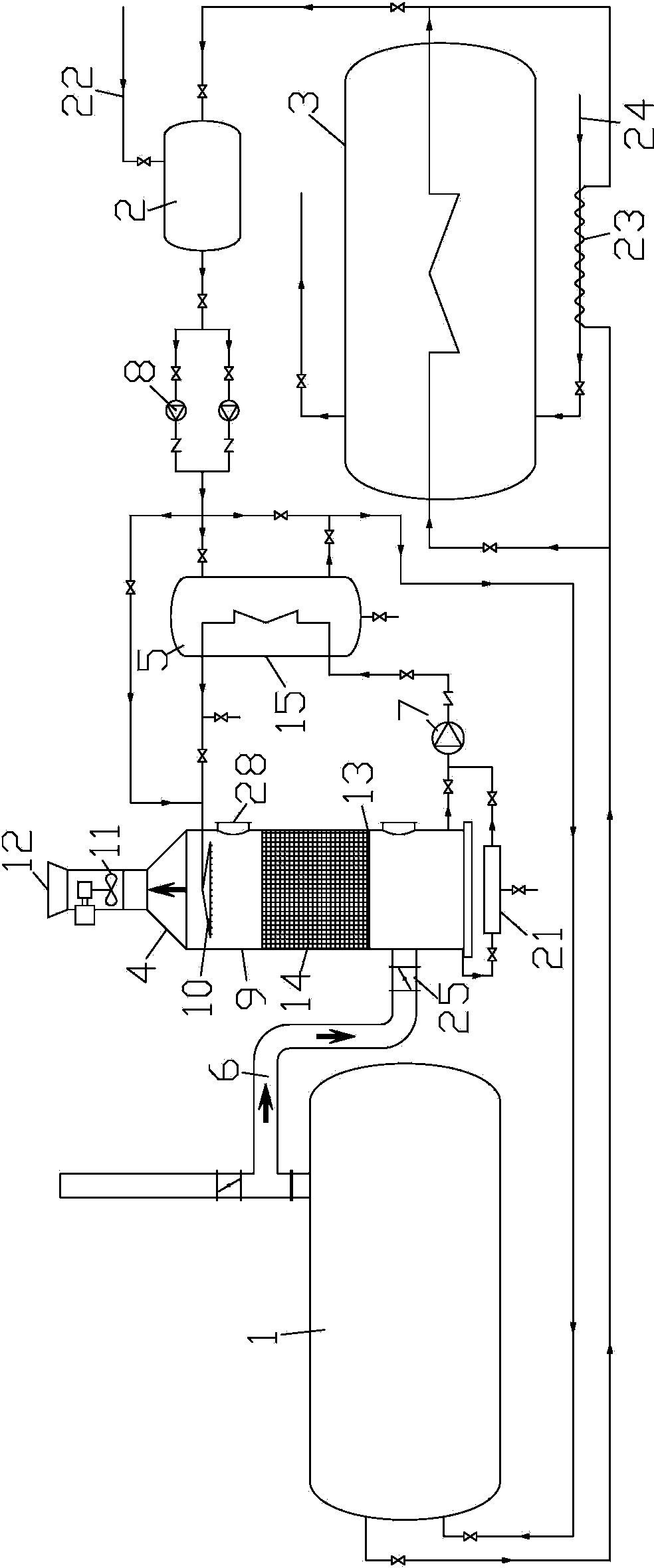
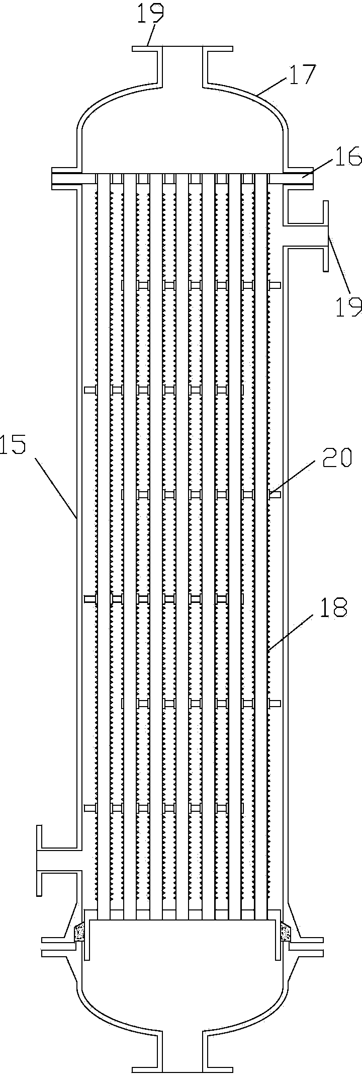
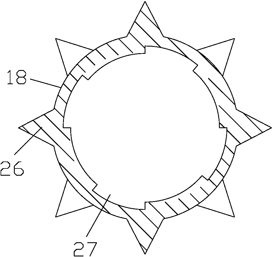
[0021] Such as figure 1 , figure 2 , image 3 and Figure 4 As shown, the waste heat recovery and emission reduction device of the crude oil gathering and transportation heating furnace tail gas involved in the present invention includes a heating furnace 1, a return tank 2 and a crude oil preheating device 3, and the heating furnace 1 is provided with a water inlet and an outlet The water outlet, the heating furnace 1 heats the medium through the combustion of natural gas, the water outlet of the heating furnace 1 is connected with the water inlet end of the crude oil preheating device 3, and the water outlet end of the crude oil preheating device 3 is connected with the return tank 2 connected to the water return port, and also includes exhaust waste heat recovery device 4 and anti-corrosion heat exchanger 5, the heating furn...


PUM


Abstract

The invention relates to a crude oil gathering and transportation heating furnace tail gas waste heat recycle and emission reduction device. The crude oil gathering and transportation heating furnace tail gas waste heat recycle and emission reduction device comprises a heating furnace, a water return tank and a crude oil preheaing device, and also comprises a tail gas waste heat recoverer and an anticorrosion heat exchanger, wherein a smoke guide channel is arranged in the heating furnace; the other end of the smoke guide channel is communicated with the lower part of the tail gas waste heat recoverer; a water inlet pipe and a water outlet pipe in the heat release end of the anticorrosion heat exchanger are respectively communicated with the water outlet end and the water inlet end of the tail gas waste heat recoverer; a water inlet pipe of the heated end of the anticorrosion heat exchanger is connected with the water outlet of the water return tank; the water outlet pipe of the heated end of the anticorrosion heat exchanger is connected with the water inlet of the heating furnace; crude oil gathering and transportation heating furnace tail gas is guided into the tail gas waste heat recoverer, a lot of sensible heat in the recovered tail gas and the condensation latent heat of vapour contained in the tail gas are capable of improving the thermal efficiency of the heating furnace to over 10%, sulfur oxide, nitric oxide, carbon monoxide, carbon dioxide, fly ash and smoke in the tail gas can partially and wholly dissolve in water, and the environment protection is facilitated.

Description

technical field [0001] The invention relates to a heating furnace waste heat recovery and emission reduction device, in particular to a crude oil collection and transportation heating furnace tail gas waste heat recovery and utilization and emission reduction device. Background technique [0002] At present, one or more heating furnaces using natural gas as fuel are generally used in my country's crude oil gathering and transportation joint stations to complete the crude oil preheating work in the process of crude oil gathering and transportation. For main equipment with a water temperature of 80-90°C, the crude oil is preheated by circulating water through preheating of the crude oil and heat tracing of the external pipeline; , the volume composition of water vapor in the tail gas is between 15% and 19%, the discharge temperature is between 180 and 300°C, and there are sulfur oxides, nitrogen oxides, carbon monoxide and carbon dioxide, as well as fly ash and smoke and other p...

Claims


Application Information

Patent Timeline
IPC IPC(8): F24H7/04F24H9/00F23J15/06F28F1/40F28F19/00
CPCY02E20/30
Inventor 李宝山房震宇王方周沈和平陈修凤樊川郭银春
Owner 中能纪(北京)国际科技有限公司
Learn More