Air conditioner waste heat and waste energy power generation device

A technology for power generation and waste energy, applied in air conditioning systems, space heating and ventilation, generators/motors, etc., can solve problems such as power consumption, reduce power consumption, improve power generation efficiency, and prolong service life.

Active Publication Date: 2014-12-31
成都中环资(集团)有限公司
View PDF5 Cites 14 Cited by
  • Summary
  • Abstract
  • Description
  • Claims
  • Application Information

AI Technical Summary

Problems solved by technology

In addition, when the air conditioner is in standby, it also consumes electricity. According to statistics, the air conditioner also consumes about 26.7 kWh of electricity in one year.

Method used


Image

  • Air conditioner waste heat and waste energy power generation device
  • Air conditioner waste heat and waste energy power generation device
  • Air conditioner waste heat and waste energy power generation device

Examples


Embodiment 1

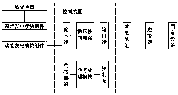
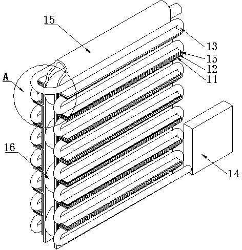
[0035] This embodiment is realized through the following technical solutions: including a heat exchanger, a thermoelectric power generation module assembly, a kinetic energy power generation module assembly and a control device; the heat exchanger includes a condensation pipe 16 and a finned cooling plate 15; The cross-section of the plate 15 is U-shaped, covering the outside of the condensation pipe 16 of the heat exchanger and clinging to the outer wall of the condensation pipe 16; And the cold medium storage 14; the cold medium storage 14 is internally connected to the cold medium circulation conduit 13, including a circulation pump and a coolant nozzle; the cold medium circulation conduit 13 is arranged in an S shape and embedded in the finned cooling plate 15 In the fin interval; the cold medium circulation conduit 13, the cold end conduction plate 12, the thermoelectric power generation module 11 and the fin cooling plate 15 are sequentially fastened and connected; the ki...

Embodiment 2

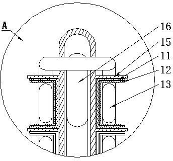
[0042] This embodiment is further optimized on the basis of the above embodiments. Further, the cross-section of the semiconductor thermoelectric power generation module 11 is U-shaped, and the cross-section of the cold end conduction plate 12 is U-shaped; the side wall of the cold medium circulation conduit 13 and the cold end The U-shaped inner surface of the conductive plate 12 is in close contact, the U-shaped outer surface of the cold-end conductive plate 12 is in close contact with the 11U-shaped inner surface of the semiconductor thermoelectric power generation module, and the 11U-shaped outer surface of the semiconductor thermoelectric power generation module is in close contact with the surface of the fin cooling plate 15 .

[0043] The U-shaped cold-end conduction plate 12 is tightly nested in the U-shaped thermoelectric power generation module 11, and the U-shaped inner surface of the U-shaped cold-end conduction plate 12 is in close contact with the conduit of the c...

Embodiment 3

[0045] This embodiment is further optimized on the basis of the above embodiments. Further, the sensor group includes a voltage sensor and a temperature sensor; the voltage sensor is connected to the battery pack; The temperature sensor A on the contact surface of the cooling plate 15 and the temperature sensor B provided on the contact surface of the thermoelectric power generation module 11 and the cold end conduction plate 12 .

[0046] The voltage sensor is used to collect voltage information at both ends of the battery pack. The temperature sensor is used to collect the temperature difference between the two ends of the thermoelectric power generation module 11; the temperature sensor A is used to collect the temperature of the contact surface between the thermoelectric power generation module 11 and the fin cooling plate 15; the temperature sensor B is used to collect the temperature difference The temperature of the contact surface between the power generation module 11...


PUM


Abstract

The invention discloses an air conditioner waste heat and waste energy power generation device, which is arranged in an air conditioner outdoor unit. The air conditioner waste heat and waste energy power generation device comprises a heat exchanger, a temperature difference power generation module assembly, a kinetic energy power generation module assembly and a control device, wherein the heat exchanger comprises condenser pipes and fin cooling plates; the section of each fin cooling plate is of a U shape; each fin cooling plate covers the outside of each condenser pipe of the heat exchanger and is tightly fit to the outer wall of the condenser pipe; the heat exchanger and the temperature difference power generation module assembly are fit; the temperature difference power generation module assembly and the kinetic energy power generation module assembly are respectively connected with the control device to supply power to electric equipment. When an air conditioner works, the temperature difference generated by waste heat in a cold energy pipe is used by the temperature difference power generation module assembly to generate power, waste energy generated by the rotation of a fan is utilized by the kinetic energy power generation module assembly to generate power, converted electric energy can be used for supplying power to the electric equipment by the control device, mains supply consumed by the air conditioner is reduced, waste heat discharge can be effectively reduced, new pollution is not generated, energy is saved, and the environment is protected.

Description

technical field [0001] The invention relates to the technical field of air-conditioning equipment, in particular to an air-conditioning waste heat and waste energy power generation device. Background technique [0002] Statistics as of December 2013 show that the number of air conditioners in my country has exceeded 600 million units. Calculated by using 1,000 hours per year, the annual power consumption of air conditioners alone is more than 600 billion kWh. Moreover, every 1 kilowatt-hour of electricity consumed is equivalent to consuming 0.37 kilograms of standard coal and emitting 1 kilogram of carbon dioxide and other greenhouse gases. That is to say, the current use of air conditioners in my country alone consumes 222 million tons of standard coal and emits 600 million tons of carbon dioxide and other greenhouse gases every year. In addition, the air conditioner also consumes electricity when it is in standby. According to statistics, the air conditioner also consumes...

Claims


Application Information

Patent Timeline
IPC IPC(8): H02N11/00F24F12/00
Inventor 潘志成章骁邱恋邱小丽赵媛张强刘纪景李慧强陈丹丹赖波
Owner 成都中环资(集团)有限公司
Why Eureka
Try Eureka