
Method and system for improving thermal efficiency of setting machine

A setting machine, thermal efficiency technology, applied in heating/cooling fabrics, textiles and papermaking, fabric surface trimming, etc. Effectiveness of utilization efficiency and thermal efficiency improvement

Inactive Publication Date: 2015-01-07
GUANGZHOU INST OF ENERGY CONVERSION - CHINESE ACAD OF SCI
View PDF5 Cites 11 Cited by
  • Summary
  • Abstract
  • Description
  • Claims
  • Application Information

AI Technical Summary

Problems solved by technology

The lost heat not only wastes energy but also causes environmental pollution. Therefore, it is imperative to recover the waste heat of the heat setting machine
In addition, as the outlet humidity of the cloth and the humidity of the humid air in the oven decrease, the energy efficiency of the setting machine drops sharply: when the outlet humidity of the cloth drops from 8% to 3%, the exergy efficiency of the setting machine heated by circulating heat transfer oil Can be reduced from 14% to 8%

Method used


Image

  • Method and system for improving thermal efficiency of setting machine
  • Method and system for improving thermal efficiency of setting machine

Examples


Embodiment 1

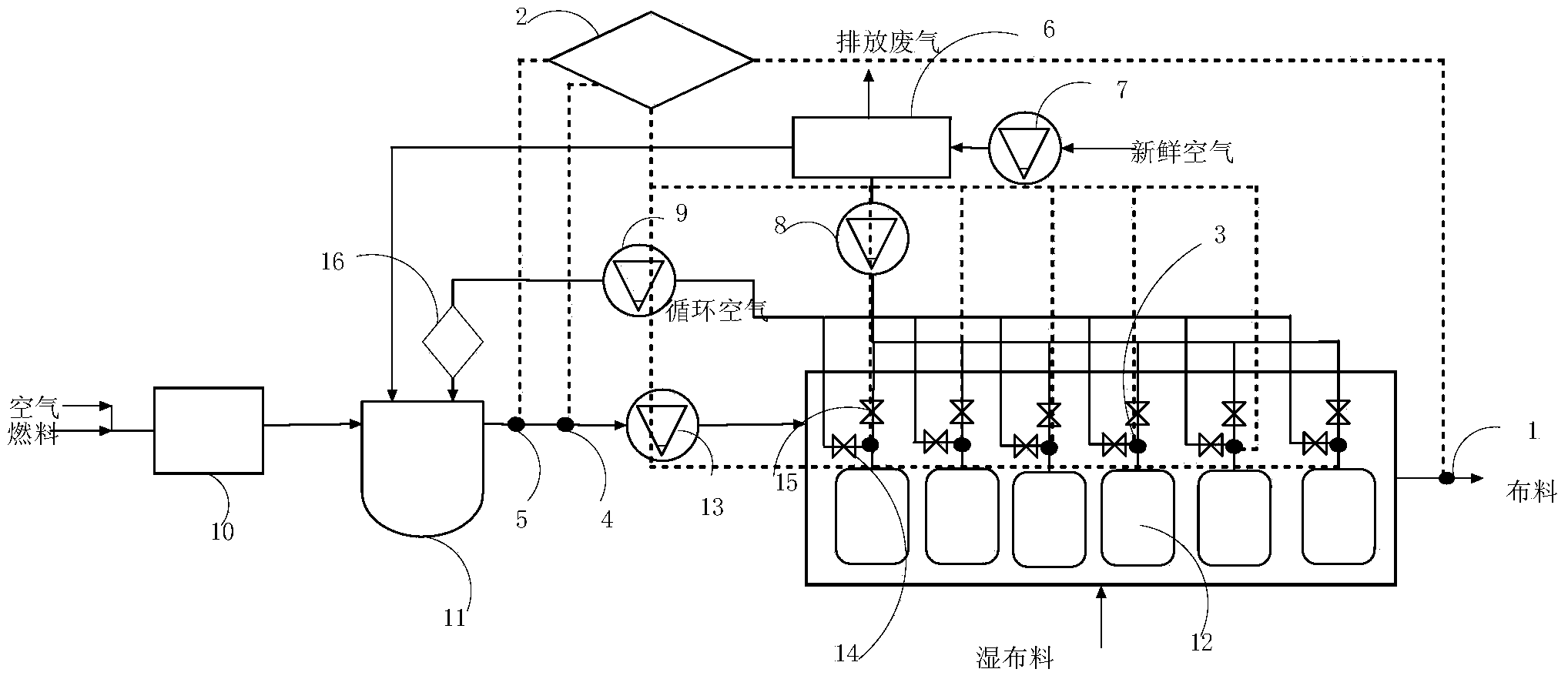
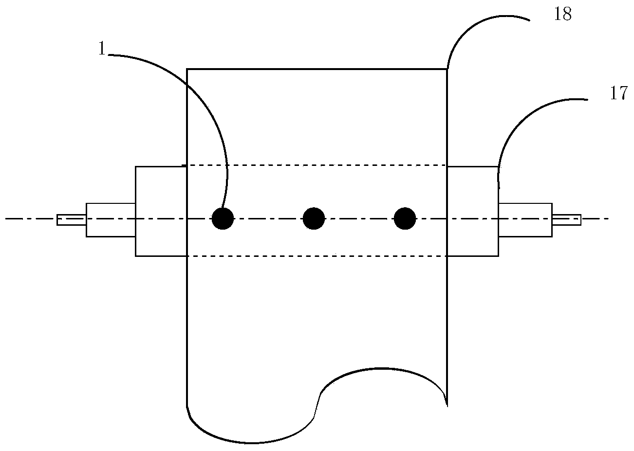
[0025] The present embodiment is the setting of cotton cloth: a kind of system that improves the thermal efficiency of the setting machine, it comprises the cloth guiding roller 17 that is located at the outlet of the shaping machine chain, the cloth 18 is laid on the cloth guiding roller 17, on the cloth guiding roller 17, The position below the cloth 18 is equipped with three cloth moisture content detection heads 1, which are respectively located on the left, middle and right of the cloth 18 plane; it also includes a burner 10 that provides heat to the dry air, and the input end of the burner 10 inputs fresh air and fuel , the output end of the burner 10 is connected to the mixer 11, and the input end of the mixer 11 is also respectively connected to a waste heat recovery heat exchanger 6 and a filter 16, and the input end of the waste heat recovery heat exchanger 6 is respectively connected to a fresh air induced draft fan 7 and exhaust blower 8, the input end of filter 16 ...

Embodiment 2

[0033]The present embodiment is the setting of cotton cloth: a kind of system that improves the thermal efficiency of the setting machine, it comprises the cloth guiding roller 17 that is located at the outlet of the shaping machine chain, the cloth 18 is laid on the cloth guiding roller 17, on the cloth guiding roller 17, The position below the cloth 18 is equipped with three cloth moisture content detection heads 1, which are respectively located on the left, middle and right of the cloth 18 plane; it also includes a burner 10 that provides heat to the dry air, and the input end of the burner 10 inputs fresh air and fuel , the output end of the burner 10 is connected to the mixer 11, and the input end of the mixer 11 is also respectively connected to a waste heat recovery heat exchanger 6 and a filter 16, and the input end of the waste heat recovery heat exchanger 6 is respectively connected to a fresh air induced draft fan 7 and exhaust blower 8, the input end of filter 16 i...

Embodiment 3

[0041] The present embodiment is the setting of cotton cloth: a kind of system that improves the thermal efficiency of the setting machine, it comprises the cloth guiding roller 17 that is located at the outlet of the shaping machine chain, the cloth 18 is laid on the cloth guiding roller 17, on the cloth guiding roller 17, The position below the cloth 18 is equipped with three cloth moisture content detection heads 1, which are respectively located on the left, middle and right of the cloth 18 plane; it also includes a burner 10 that provides heat to the dry air, and the input end of the burner 10 inputs fresh air and fuel , the output end of the burner 10 is connected to the mixer 11, and the input end of the mixer 11 is also respectively connected to a waste heat recovery heat exchanger 6 and a filter 16, and the input end of the waste heat recovery heat exchanger 6 is respectively connected to a fresh air induced draft fan 7 and exhaust blower 8, the input end of filter 16 ...


PUM


Abstract

The invention discloses a system for improving the thermal efficiency of a setting machine. Three cloth water content probes are arranged above a cloth guiding roller and below a piece of cloth; the output end of a burner is connected with a mixer; the input end of the mixer is also respectively connected with an afterheat recycling heat exchanger and a filter; the input end of the afterheat recycling heat exchanger is respectively connected with a fresh air draught fan and an air exhauster; the input end of the filter is connected with a circulating air draught fan; the output ends of ovens are divided into two branches; one of the branches is connected with the air exhauster by virtue of an exhaust valve while the other of the branches is connected with the circulating air draught fan by virtue of a circulating air valve; the output end of the oven is also provided with an air humidity infrared probe; an outlet of the mixer is connected with an air flow meter, a temperature sensor and a dry air draught fan. The system also comprises a frequency converter for adjusting the opening / closing of the circulating air valve, the opening / closing of the air exhaust valve, the action of chains of the setting machine and the action of the fresh air draught fan according to signals sent by the water content probes, the air humidity infrared probe, the air flow meter and the temperature sensor.

Description

technical field [0001] The invention relates to a method for improving thermal efficiency of a sizing machine, and also relates to a system for realizing the method. Background technique [0002] The setting machine is a device that uses hot air to dry, arrange and shape the fabric, and is one of the main energy-consuming equipment in the textile dyeing and finishing industry. A single setting machine consumes 600,000 to 1,000,000 kcal of energy. It is estimated that the heat energy consumed by fabric processing and setting accounts for only 29%, the heat loss of the body accounts for about 10%, and the remaining large amount of heat energy (over 60%) is lost to the atmosphere with the exhaust gas. middle. The lost heat not only wastes energy but also causes environmental pollution. Therefore, it is imperative to recover the waste heat of the heat setting machine. In addition, as the outlet humidity of the cloth and the humidity of the humid air in the oven decrease, the e...

Claims


Application Information

Patent Timeline
Patent Type & Authority Applications(China)
IPC IPC(8): D06C7/02
CPCD06C7/02
Inventor 尹华郭华芳李家杰
Owner GUANGZHOU INST OF ENERGY CONVERSION - CHINESE ACAD OF SCI
Learn More