Novel self-heat-preserving system of cast-in-place combined type wall body
A self-insulation system, combined wall technology, applied in the direction of insulation, walls, building components, etc., can solve the problems of poor durability, easy cracking of walls, and poor fire safety.
Inactive Publication Date: 2015-01-07
绿建科技集团新型建材高技术有限公司
15 Cites 0 Cited by
AI-Extracted Technical Summary
Problems solved by technology
[0003] At present, there are the following outstanding problems in wall insulation technology and insulation materials at home and abroad: First, there are poor fire safety
[0015] The technical problem to be solved by the present invention is: to overcome the fatal defects such as poor fireproof performance, poor durability, poor rainwater leakage resistance and easy cracking of the wall body of most of the current thermal insulation...
Method used
As shown in Figure 14 and Figure 15, a new type of cast-in-place combined wall self-insulation system is characterized in that the self-insulation wall 1 of the A-type composite insulation block is built by masonry with the A-type composite insulation block 3 The two ends of self-insulation wall 1 of A-type composite insulation block are connected to self-insulation shear wall 5, and the contact surface between both ends of A-type composite insulation block self-insulation wall 1 and self-insulation shear wall 5 is glued with masonry mortar Connect; the cavity between the A-type composite thermal insulation block self-insulation wall 1 and the self-insulation beam 8 uses a high-strength composite thermal insulation board as an outer formwork or an inner formwork, and then casts in-situ concrete, and connects the high-strength composite thermal insulation board through the connecting fixture 23 It is firmly connected with the cast-in-place concrete to form the first cast-in-place self-insulation wall 9; the first layer of blocks in the B-type composite insulation block self-insulation wall 2 is built by C-type composite insulation blocks 12, and the B-type composite insulation block 12 is built. Type B composite thermal insulation block self-insulation wall 2 is built with B-type composite thermal insulation block 6, so that the block masonry mortar joints of A-type composite thermal insulation block self-thermal insulation wall 1 are not facing the B-type composite thermal insulation block. The thermal insulation block self-insulates the block masonry mortar joints of the thermal insulation wall 2 to reduce the heat loss caused by the convection between the blocks due to the horizontal masonry mortar joints, and enhance the thermal insulation effect of the wall; the B-type composite thermal insulation block self- The two ends of the thermal insulation wall 2 are close to the inner surface of the self-insulation shear wall 5, and there is an air layer 7 between the self-insulation wall 1 of the A-type composite insulation block and the self-insulation wall 2 of the B-type composite insulation block, and the A-type There are tie bars 13 between the self-insulating wall body 1 of the composite thermal insulation block and the self-insulation wall body 2 of the composite thermal insulation block, and an insulation layer is made at the contact part between the air layer 7 and the surroundings of the doors and windows to seal the air layer 7 , the cavity between the top end face of the self-insulating wall 2 of the B-type composite thermal insulation block and the self-insulation beam 8 uses a high-strength composite thermal insulation board as an outer formwork or an inner formwork, and then casts in-situ concrete, and the high-strength composite thermal insulation is connected through the connecting fixture 23 The board is firmly connected with the cast-in-place concrete to form the second cast-in-place self-insulation wall 10 .
As shown in Figure 16 and Figure 17, a new type of cast-in-place combined wall self-insulation system is characterized in that the A-type composite insulation block 3 is used to build the A-type composite insulation block self-insulation wall 1 The two ends of self-insulation wall 1 of A-type composite insulation block are connected with self-insulation column 4 and self-insulation shear wall 5 respectively, and the two ends of A-type composite insulation block self-insulation wall 1 are connected with self-insulation column 4 and self-insulation shear The contact surface of the force wall 5 is bonded with masonry mortar; the cavity between the self-insulating wall 1 and the self-insulating beam 8 of the A-type composite thermal insulation block uses a high-strength composite thermal insulation board as an outer formwork or an inner formwork, and then cast-in-place concrete , the high-strength composite thermal insulation board and the cast-in-place concrete are firmly connected together through the connecting fixture 23 to form the first cast-in-situ self-insulation wall 9; a layer of blocks in the self-insulation wall 2 of the B-type composite thermal insulation block is composed of C-type composite thermal insulation block 12 is built by masonry, and the rest of B-type composite thermal insulation block self-insulation wall 2 then adopts B-type composite thermal insulation block 6 to build by laying bricks or stones, makes A-type composite thermal insulation block self-insulation wall 1 masonry The mortar joints of the block masonry are not directly facing the mortar joints of the self-insulating wall 2 of the B-type composite thermal insulation block, so as to reduce the heat loss caused by the convection between the blocks and enhance the insulation of the wall Thermal insulation effect; Type B composite thermal insulation block self-thermal insulation wall 2 is connected to self-thermal insulation column 4 at one end, and one end is close to the inner side of self-thermal insulation shear wall 5, and A-type composite thermal insulation block self-thermal insulation wall 1 is combined with B-type There is an air layer 7 between the thermal insulation block self-insulation wall 2, and there is a tie steel bar 13 between the A-type composite thermal insulation block self-thermal insulation wall 1 and the B-type composite thermal insulation block self-thermal insulation wall 2, and the air layer 7 The part in contact with the door and window is used as an insulation layer, and the air layer 7 is closed. The cavity between the top end surface of the self-insulation wall 2 of the B-type composite insulation block and the self-insulation beam 8 uses a high-strength composite insulation board as an outer template or The inner formwork is then cast-in-place concrete, and the high-strength composite thermal insulation board and the cast-in-place concrete are firmly connected together through the connecting fixture 23 to form the second cast-in-place self-insulation wall 10 .
As shown in Figure 3 and Figure 6, a new type of cast-in-place combined wall self-insulation system is characterized in that the A-type composite insulation block 3 is used to build the A-type composite insulation block self-insulation wall 1 The two ends of the A-type composite thermal insulation block self-insulation wall 1 are connected to the self-insulation column 4, and the contact surfaces between the two ends of the A-type composite insulation block self-insulation wall 1 and the self-insulation column 4 are bonded with masonry mortar; The cavity between the self-insulating wall 1 and the self-insulating beam 8 of the composite insulation block uses a high-strength composite insulation board as an outer formwork or an inner formwork, and then cast-in-situ concrete, and connects the high-strength composite insulation board and the cast-in-place concrete Firmly connected together to form the first cast-in-place self-insulation wall 9; the first layer of blocks in the B-type composite insulation block self-insulation wall 2 is built by C-type composite insulation blocks 12, and the B-type composite insulation block The rest of the block self-insulation wall 2 is built with B-type composite insulation blocks 6, so that the block masonry mortar joints of the A-type composite insulation blocks self-insulation wall 1 are not facing the B-type composite insulation blocks. The block masonry mortar...
Abstract
The invention provides a novel self-heat-preserving system of a cast-in-place combined type wall body. The system is characterized in that a self-heat-preserving column, a self-heat-preserving shear wall, a self-heat-preserving beam and a self-heat-preserving floor slab are organically combined with a self-heat-preserving wall body, wherein the self-heat-preserving wall body is formed by building composite heat-preserving building blocks; meanwhile, other parts without heat preserving and insulating function of the wall body are processed by heat preserving and insulating, so as to form a complete wall body self-heat-preserving system. The wall body self-heat-preserving has the outstanding advantages that the energy saving effect is high, the construction is convenient, the fireproof performance is high, and the crack resistance, water resistance and water penetration resistance are outstanding; the critical defects of poor fireproof performance, poor durability, low rainwater leakage resistance, and easy cracking of the wall body of most of the current heat preserving wall bodies can be overcome; the economic benefit and social benefit can be increased by the popularization and application of the technical system.
Application Domain
Construction materialWalls +3
Technology Topic
Floor slabEngineering +8
Image
Examples
- Experimental program(5)
Example Embodiment
[0084] Embodiment 1
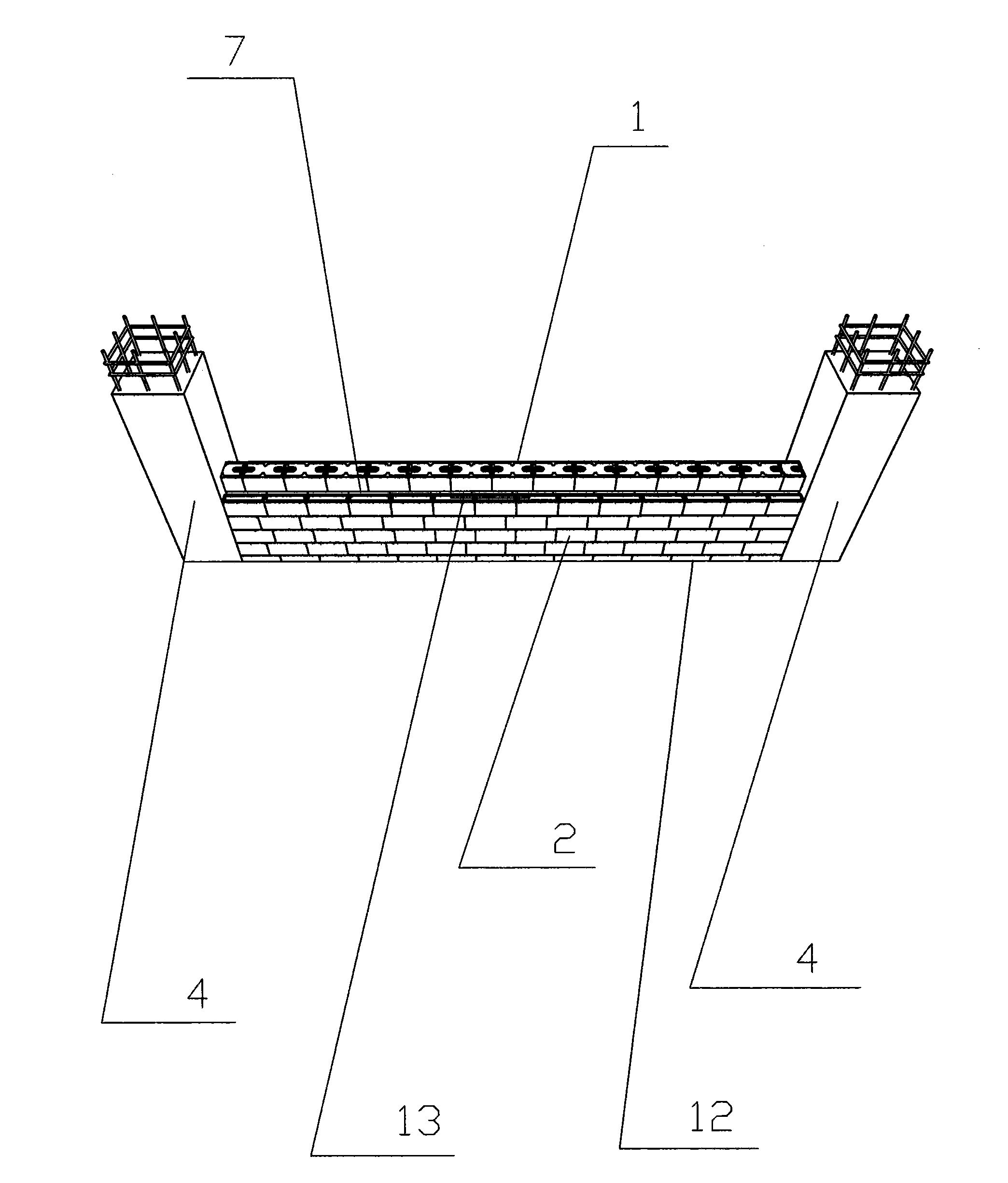
[0085] (1) Construction and practice of self-insulating columns, self-insulating shear walls, self-insulating beams and self-insulating floors:
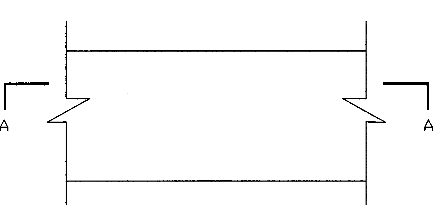
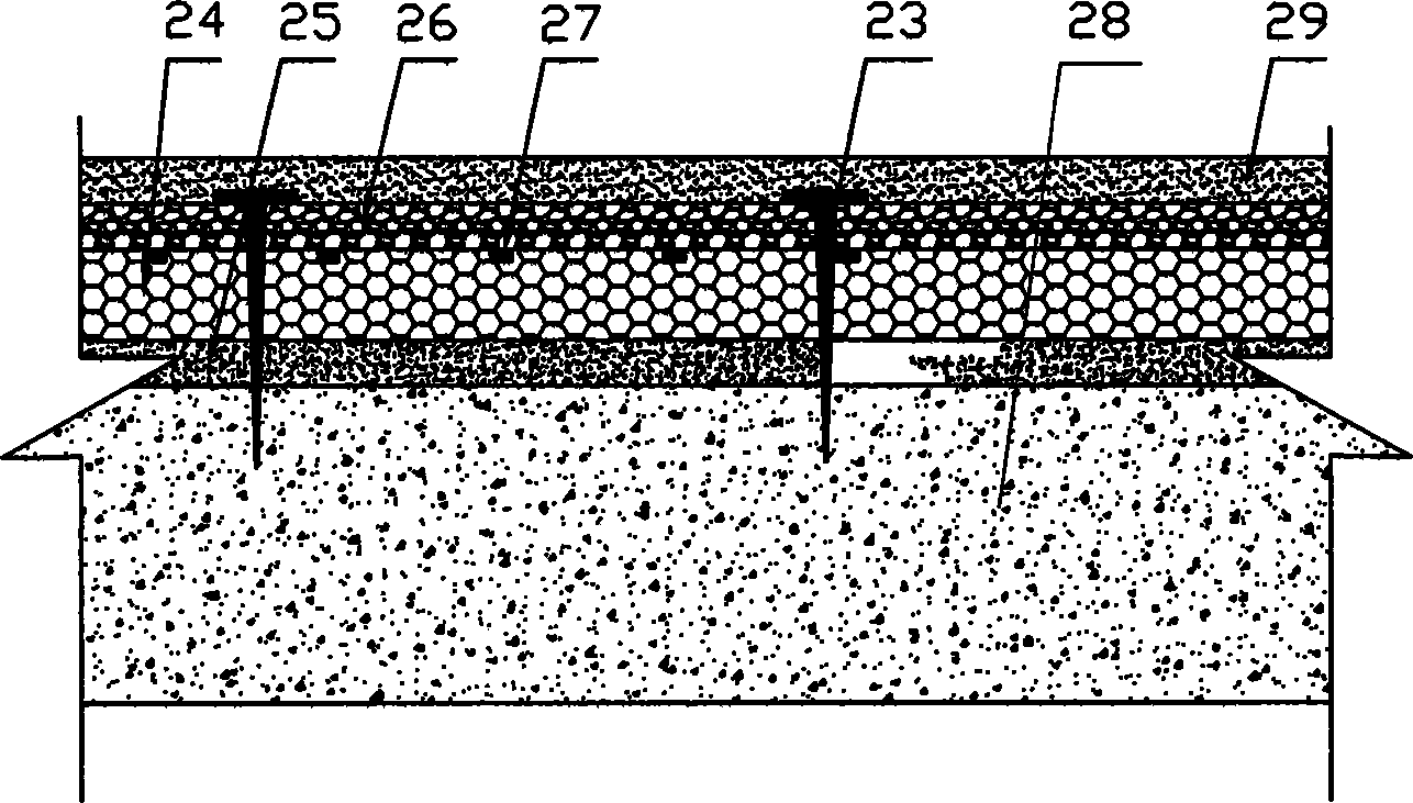
[0086] The cast-in-place self-insulating wall structure includes self-insulating columns, self-insulating shear walls, self-insulating beams and self-insulating floors. like figure 1 , figure 2As shown, the high-strength composite thermal insulation board is composed of a polystyrene board 24, an inner reinforcement layer 25, an outer reinforcement layer 26 and a reinforcement rib 27. The inner reinforcement layer 25 is arranged on the inside of the polystyrene board 24, and the reinforcement rib 27 is arranged on the outer side of the polystyrene board 24. , the outer reinforcing layer 26 is arranged outside the reinforcing rib 27 . During construction, the high-strength composite thermal insulation board is placed on the outer side of the steel bars of the bound columns, walls, beams and floors, and a plurality of connecting fixtures 23 are arranged on the high-strength composite thermal insulation board. By pouring concrete, the high-strength composite thermal insulation board, connection The fixing part 9 is poured together with the cast-in-place concrete to form a self-insulating column, a self-insulating shear wall, a self-insulating beam and a self-insulating floor slab.
[0087] (2) The structure and practice of the wall self-insulation system:
[0088] like image 3 , Image 6 As shown, a new cast-in-place combined wall self-insulation system is characterized in that the A-type composite insulation block self-insulation wall 1 is built with A-type composite insulation blocks 3, and the A-type composite insulation block self-insulation The two ends of the wall 1 are connected to the self-insulation column 4, and the contact surface between the two ends of the A-type composite insulation block self-insulation wall 1 and the self-insulation column 4 is bonded with masonry mortar; the A-type composite insulation block self-insulation wall 1 The cavity between the self-insulating beam 8 uses a high-strength composite insulation board as an outer formwork or an inner formwork, and then casts concrete, and the high-strength composite insulation board and the cast-in-place concrete are firmly connected through the connecting fixture 23 to form the first The cast-in-place self-insulation wall 9; the first layer of blocks in the B-type composite insulation block self-insulation wall 2 is built by C-type composite insulation blocks 12, and the rest of the B-type composite insulation block self-insulation wall 2 The B-type composite thermal insulation block 6 is used for masonry, so that the block masonry mortar joint of the A-type composite thermal insulation block self-insulation wall 1 is not directly facing the block masonry of the B-type composite thermal insulation block self-insulation wall 2 Mortar joints, to reduce the heat loss caused by convection between the blocks due to horizontal masonry mortar joints, and enhance the thermal insulation effect of the wall; the B-type composite thermal insulation block self-insulation wall 2 is connected to the self-insulation column 4 at both ends, A There is an air layer 7 between the self-insulating wall 1 of type A composite thermal insulation block and the self-insulation wall 2 of type B composite thermal insulation block, and the self-insulation wall 1 of type A composite thermal insulation block and the self-insulation wall of type B composite thermal insulation block There are tie bars 13 between the body 2, and an insulation layer is made at the contact part between the air layer 7 and the door and the window, and the air layer 7 is closed. On the self-insulation lintel 21 at the top of the door and the window Masonry B-type composite thermal insulation block 6; the cavity between the top end face of the B-type composite thermal insulation block self-insulation wall 2 and the self-insulation floor 22 uses a high-strength composite thermal insulation board as the outer formwork or inner formwork, and then casts in-situ concrete, The high-strength composite thermal insulation board and the cast-in-place concrete are firmly connected together through the connecting fixture 23 to form the second cast-in-situ self-insulation wall 10 .
[0089] In this technical solution, the A-type composite thermal insulation block is a single-cavity H-core composite thermal insulation block, or a double-cavity composite thermal insulation block, or a double-cavity composite thermal insulation block. like Figure 9 As shown, the single-cavity H-core composite thermal insulation block is composed of a single-cavity H-core composite thermal insulation block concrete shell 15 and an insulating material 16 filled in the cavity of the concrete shell. The groove 17 of the length of the cold and heat bridge. like Figure 10 As shown, the double-cavity composite thermal insulation block is composed of the concrete shell of the double-cavity composite thermal insulation block and the thermal insulation material filled in the cavity of the concrete shell. There is a groove extending the length of the cold and thermal bridge in the middle of the two end faces of the concrete shell. groove. like Figure 11 As shown, a double-cavity composite thermal insulation block is composed of a concrete shell of a double-cavity composite thermal insulation block, an insulating material filled in a longer cavity in the concrete shell, and two other smaller cavities. The concrete shell There is a groove extending the length of the cold and heat bridge in the middle of the end faces of the two ends of the body.
[0090] B-type composite thermal insulation block is a single-cavity one-shaped composite thermal insulation block, or a double-cavity Japanese-shaped composite thermal insulation block. like Figure 12 As shown, the single-cavity inline-shaped composite thermal insulation block is composed of a single-cavity inline-shaped composite thermal insulation block concrete shell 19 and an insulating material 16 filled in the cavity of the concrete shell. like Figure 13 As shown, the double-cavity Japanese-shaped composite thermal insulation block is composed of a double-cavity Japanese-shaped composite thermal insulation block concrete shell and an insulating material filled in the cavity of the concrete shell.
[0091] The width of the A-type composite thermal insulation block is greater than that of the B-type composite thermal insulation block.
[0092] The height of the C-type composite thermal insulation block is lower than that of the B-type composite thermal insulation block.
Example Embodiment
[0093] Embodiment 2
[0094] (1) Construction and practice of self-insulating columns, self-insulating shear walls, self-insulating beams and self-insulating floors:
[0095] The cast-in-place self-insulating wall structure includes self-insulating columns, self-insulating shear walls, self-insulating beams and self-insulating floors. like figure 1 , figure 2 As shown, the high-strength composite thermal insulation board is composed of a polystyrene board 24, an inner reinforcement layer 25, an outer reinforcement layer 26 and a reinforcement rib 27. The inner reinforcement layer 25 is arranged on the inside of the polystyrene board 24, and the reinforcement rib 27 is arranged on the outer side of the polystyrene board 24. , the outer reinforcing layer 26 is arranged outside the reinforcing rib 27 . During construction, the high-strength composite thermal insulation board is placed on the outer side of the steel bars of the bound columns, walls, beams and floors, and a plurality of connecting fixtures 23 are arranged on the high-strength composite thermal insulation board. By pouring concrete, the high-strength composite thermal insulation board, connection The fixing part 9 is poured together with the cast-in-place concrete to form a self-insulating column, a self-insulating shear wall, a self-insulating beam and a self-insulating floor slab.
[0096] (2) The structure and practice of the wall self-insulation system:
[0097] like Figure 4 , Figure 7 As shown, a new cast-in-place combined wall self-insulation system is characterized in that the A-type composite insulation block self-insulation wall 1 is built with A-type composite insulation blocks 3, and the A-type composite insulation block self-insulation The two ends of the wall 1 are connected to the self-insulating shear wall 5, and the contact surfaces between the two ends of the self-insulating wall 1 of the A-type composite insulation block and the self-insulation shear wall 5 are bonded with masonry mortar; The cavity between the thermal insulation wall 1 and the self-insulation beam 8 uses a high-strength composite thermal insulation board as an outer template or an inner template, and then casts concrete, and connects the high-strength composite thermal insulation board and the cast-in-place concrete firmly through the connecting fixture 23 , forming the first cast-in-place self-insulation wall 9; the first layer of blocks in the B-type composite insulation block self-insulation wall 2 is built by C-type composite insulation blocks 12, and the B-type composite insulation block self-insulation wall The rest of 2 is built with B-type composite thermal insulation blocks 6, so that the block masonry mortar joints of the A-type composite thermal insulation block self-insulation wall 1 are not facing the B-type composite thermal insulation block self-insulation wall 2. Block masonry mortar joints to reduce the heat loss caused by convection between the blocks due to horizontal masonry mortar joints, and enhance the thermal insulation effect of the wall; B-type composite thermal insulation blocks self-insulation wall 2 both ends are connected and self-insulation Shear wall 5, there is an air layer 7 between self-insulation wall 1 of type A composite insulation block and self-insulation wall 2 of type B composite insulation block, self-insulation wall 1 of type A composite insulation block and type B composite There are tie bars 13 between the self-insulating wall body 2 of the heat-insulating block, and an insulation layer is made at the contact part between the air layer 7 and the surroundings of the door and the window to seal the air layer 7, and the self-insulating lintel on the upper part of the door and the upper part of the window Build B-type composite insulation block 6 on the self-insulation lintel 21; the cavity between the top end face of the B-type composite insulation block self-insulation wall 2 and the self-insulation floor 22 uses a high-strength composite insulation board as an outer formwork or an inner formwork , and then cast-in-place concrete, the high-strength composite thermal insulation board and the cast-in-place concrete are firmly connected together through the connecting fixture 23 to form the second cast-in-place self-insulation wall 10 .
[0098] In this technical solution, the A-type composite thermal insulation block is a single-cavity H-core composite thermal insulation block, or a double-cavity composite thermal insulation block, or a double-cavity composite thermal insulation block. like Figure 9 As shown, the single-cavity H-core composite thermal insulation block is composed of a single-cavity H-core composite thermal insulation block concrete shell 15 and an insulating material 16 filled in the cavity of the concrete shell. The groove 17 of the length of the cold and heat bridge. like Figure 10 As shown, the double-cavity composite thermal insulation block is composed of the concrete shell of the double-cavity composite thermal insulation block and the thermal insulation material filled in the cavity of the concrete shell. There is a groove extending the length of the cold and thermal bridge in the middle of the two end faces of the concrete shell. groove. like Figure 11 As shown, a double-cavity composite thermal insulation block is composed of a concrete shell of a double-cavity composite thermal insulation block, an insulating material filled in a longer cavity in the concrete shell, and two other smaller cavities. The concrete shell There is a groove extending the length of the cold and heat bridge in the middle of the end faces of the two ends of the body.
[0099] B-type composite thermal insulation block is a single-cavity one-shaped composite thermal insulation block, or a double-cavity Japanese-shaped composite thermal insulation block. like Figure 12 As shown, the single-cavity inline-shaped composite thermal insulation block is composed of a single-cavity inline-shaped composite thermal insulation block concrete shell 19 and an insulating material 16 filled in the cavity of the concrete shell. like Figure 13 As shown, the double-cavity Japanese-shaped composite thermal insulation block is composed of a double-cavity Japanese-shaped composite thermal insulation block concrete shell and an insulating material filled in the cavity of the concrete shell.
[0100] The width of the A-type composite thermal insulation block is greater than that of the B-type composite thermal insulation block.
[0101] The height of the C-type composite thermal insulation block is lower than that of the B-type composite thermal insulation block.
Example Embodiment
[0102] Embodiment 3
[0103] (1) Construction and practice of self-insulating columns, self-insulating shear walls, self-insulating beams and self-insulating floors:
[0104] The cast-in-place self-insulating wall structure includes self-insulating columns, self-insulating shear walls, self-insulating beams and self-insulating floors. like figure 1 , figure 2 As shown, the high-strength composite thermal insulation board is composed of a polystyrene board 24, an inner reinforcement layer 25, an outer reinforcement layer 26 and a reinforcement rib 27. The inner reinforcement layer 25 is arranged on the inside of the polystyrene board 24, and the reinforcement rib 27 is arranged on the outer side of the polystyrene board 24. , the outer reinforcing layer 26 is arranged outside the reinforcing rib 27 . During construction, the high-strength composite thermal insulation board is placed on the outer side of the steel bars of the bound columns, walls, beams and floors, and a plurality of connecting fixtures 23 are arranged on the high-strength composite thermal insulation board. By pouring concrete, the high-strength composite thermal insulation board, connection The fixing part 9 is poured together with the cast-in-place concrete to form a self-insulating column, a self-insulating shear wall, a self-insulating beam and a self-insulating floor slab.
[0105] (2) The structure and practice of the wall self-insulation system:
[0106] like Figure 5 , Figure 8 As shown, a new cast-in-place combined wall self-insulation system is characterized in that the A-type composite insulation block self-insulation wall 1 is built with A-type composite insulation blocks 3, and the A-type composite insulation block self-insulation The two ends of the wall 1 are respectively connected with the self-insulation column 4 and the self-insulation shear wall 5, and the contact surface between the two ends of the A-type composite insulation block self-insulation wall 1 and the self-insulation column 4 and the self-insulation shear wall 5 is built with masonry Mortar bonding; the cavity between self-insulation wall 1 and self-insulation beam 8 of A-type composite insulation block uses high-strength composite insulation board as the outer formwork or inner formwork, and then cast-in-place concrete, and the high-strength composite The insulation board and the cast-in-place concrete are firmly connected together to form the first cast-in-place self-insulation wall 9; the first layer of blocks in the B-type composite insulation block self-insulation wall 2 is built by C-type composite insulation blocks 12 , the rest of the B-type composite thermal insulation block self-thermal insulation wall 2 is built with B-type composite thermal insulation block 6, so that the block masonry mortar joints of the A-type composite thermal insulation block self-thermal insulation wall 1 are not directly facing B Type B composite thermal insulation block self-insulation wall 2 is used to reduce the heat loss caused by convection between the blocks due to horizontal masonry mortar joints, and enhance the thermal insulation effect of the wall; B-type composite thermal insulation masonry The two ends of the block self-insulation wall 2 are respectively connected with the self-insulation column 4 and the self-insulation shear wall 5, and there is an air layer between the A-type composite insulation block self-insulation wall 1 and the B-type composite insulation block self-insulation wall 2 7. There are tie bars 13 between the A-type composite thermal insulation block self-insulation wall 1 and the B-type composite thermal insulation block self-insulation wall 2, and an insulation layer is made at the contact part between the air layer 7 and the doors and windows. The air layer 7 is closed, and the B-type composite thermal insulation block 6 is built on the self-insulation lintel 21 at the upper part of the door and the self-insulation lintel 21 at the upper part of the window; The cavity between 22 uses a high-strength composite thermal insulation board as an outer formwork or an inner formwork, and then casts concrete, and connects the high-strength composite thermal insulation board and the cast-in-place concrete firmly through the connecting fixture 23 to form a second cast-in-place self-insulation wall10.
[0107] In this technical solution, the A-type composite thermal insulation block is a single-cavity H-core composite thermal insulation block, or a double-cavity composite thermal insulation block, or a double-cavity composite thermal insulation block. like Figure 9 As shown, the single-cavity H-core composite thermal insulation block is composed of a single-cavity H-core composite thermal insulation block concrete shell 15 and an insulating material 16 filled in the cavity of the concrete shell. The groove 17 of the length of the cold and heat bridge. like Figure 10 As shown, the double-cavity composite thermal insulation block is composed of the concrete shell of the double-cavity composite thermal insulation block and the thermal insulation material filled in the cavity of the concrete shell. There is a groove extending the length of the cold and thermal bridge in the middle of the two end faces of the concrete shell. groove. like Figure 11 As shown, a double-cavity composite thermal insulation block is composed of a concrete shell of a double-cavity composite thermal insulation block, an insulating material filled in a longer cavity in the concrete shell, and two other smaller cavities. The concrete shell There is a groove extending the length of the cold and heat bridge in the middle of the end faces of the two ends of the body.
[0108] B-type composite thermal insulation block is a single-cavity one-shaped composite thermal insulation block, or a double-cavity Japanese-shaped composite thermal insulation block. like Figure 12 As shown, the single-cavity inline-shaped composite thermal insulation block is composed of a single-cavity inline-shaped composite thermal insulation block concrete shell 19 and an insulating material 16 filled in the cavity of the concrete shell. like Figure 13 As shown, the double-cavity Japanese-shaped composite thermal insulation block is composed of a double-cavity Japanese-shaped composite thermal insulation block concrete shell and an insulating material filled in the cavity of the concrete shell.
[0109] The width of the A-type composite thermal insulation block is greater than that of the B-type composite thermal insulation block.
[0110] The height of the C-type composite thermal insulation block is lower than that of the B-type composite thermal insulation block.
PUM


Description & Claims & Application Information
We can also present the details of the Description, Claims and Application information to help users get a comprehensive understanding of the technical details of the patent, such as background art, summary of invention, brief description of drawings, description of embodiments, and other original content. On the other hand, users can also determine the specific scope of protection of the technology through the list of claims; as well as understand the changes in the life cycle of the technology with the presentation of the patent timeline. Login to view more.