High-temperature waste heat recovery system for diesel engine

A technology of waste heat recovery system and diesel engine, which is applied in the direction of charging system, mechanical equipment, steam engine device, etc., to achieve the effect of improving system performance, improving recovery system efficiency, and improving system performance

Inactive Publication Date: 2015-01-07
TIANJIN UNIV
View PDF4 Cites 13 Cited by
  • Summary
  • Abstract
  • Description
  • Claims
  • Application Information

AI Technical Summary

Problems solved by technology

[0004] Therefore, high thermal efficiency, large recovery power, simple and compact structure, and convenient layout are the main requirements for the application of waste heat recovery technology in engines, and the current technical solutions are still difficult to meet these needs

Method used


Image

  • High-temperature waste heat recovery system for diesel engine

Examples


Embodiment Construction

[0014] The system structure of the present invention will be further described below in conjunction with the accompanying drawings and through embodiments. It should be noted that this embodiment is illustrative rather than restrictive, and does not limit the protection scope of the present invention.

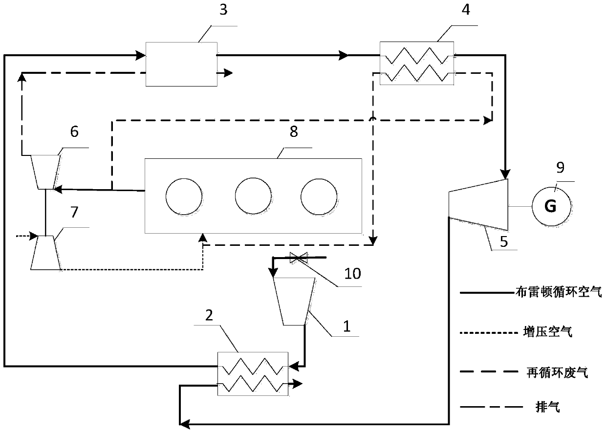
[0015] Diesel engine high temperature waste heat recovery system, including compressor, regenerator, thermoelectric generator, EGR heat exchanger, expander, turbine, supercharger, engine, generator and flow control valve, etc. The system structure is as follows: the compressor 1, the regenerator 2, the thermoelectric generator 3, the EGR heat exchanger 4 and the expander 5 are sequentially connected to form a Brayton air regenerating cycle system. The air flow regulating valve 10 is connected to the air inlet of the compressor. The high-temperature exhaust gas discharged from the engine 8 is divided into two outputs: one is discharged to the atmosphere through the turbine 6 an...


PUM


Abstract

The invention discloses a high-temperature waste heat recovery system for a diesel engine. The technical scheme is that an air compressor, a regenerator, a thermo-electric generator, an EGR heat exchanger and an expander are sequentially connected to form a Brayton air regenerative cycle system, and an airflow regulating valve is connected with the air inlet of the air compressor; high-temperature exhaust gas discharged by an engine is output in two ways: one part sequentially passes through a turbine and the thermo-electric generator and then is discharged to the atmosphere, the other part is mixed with supercharged air from a supercharger through the EGR heat exchanger, and the mixture enters the air inlet of the engine; and Brayton circulating air serves as the cold end of the thermo-electric generator, exhaust passing through the turbine serves as the hot end, and the thermo-electric generator pre-heats the Brayton circulating air while outputting power. The high-temperature waste heat recovery system can efficiently utilizes high-temperature waste heat of an internal combustion engine, thereby improving the fuel economy of the internal combustion engine and lowering the heat load of the system. Meanwhile, the system has a relatively simple composition, ensures safe and environment-friendly running, is convenient and flexible in layout, and can be easily implemented in the internal combustion engine.

Description

technical field [0001] The invention belongs to the technology of energy saving and emission reduction of internal combustion engines, and in particular relates to a thermodynamic cycle system for recovering high-temperature waste heat of diesel engines. Background technique [0002] With the increasing shortage of energy and the prominence of environmental pollution, the energy saving and emission reduction of engines has attracted worldwide attention. At present, 1 / 3 of the energy released by diesel engine fuel combustion is directly discharged to the external environment through the exhaust gas, and is not used. On the other hand, the waste heat grade of recirculated exhaust gas is the highest, and the utilization of these two parts of energy is of great significance for solving problems such as energy shortage. [0003] There are many forms of recovery of engine exhaust energy. For example, turbines can be used to directly generate electricity, but this type of technolo...

Claims


Application Information

Patent Timeline
Patent Type & Authority Applications(China)
IPC IPC(8): F02G5/02F02M25/07F01K7/16F01K17/02H02N11/00F02M26/05
CPCF01K7/16F01K17/025F02G5/02F02G2250/03H02N11/002Y02T10/12
Inventor 田华张承宇舒歌群卫海桥李团兵
Owner TIANJIN UNIV
Why Eureka
Try Eureka