
A Measuring Method of Axially Moving Rope Lateral Vibration Measuring System

A technology of lateral vibration and measurement system, applied in measurement devices, measurement of ultrasonic/sonic/infrasonic waves, instruments, etc., can solve the problems of no experimental device publicly reported, no moving rope vibration test device, etc., and achieves simple structure and high integration. Effect

Inactive Publication Date: 2017-02-01
HEFEI UNIV OF TECH
View PDF4 Cites 0 Cited by
  • Summary
  • Abstract
  • Description
  • Claims
  • Application Information

AI Technical Summary

Problems solved by technology

But so far there is no public report of the relevant experimental device, and there is no mobile rope vibration test device and measurement platform that can provide multiple working conditions to verify the calculation results of the numerical algorithm.

Method used


Image

  • A Measuring Method of Axially Moving Rope Lateral Vibration Measuring System
  • A Measuring Method of Axially Moving Rope Lateral Vibration Measuring System
  • A Measuring Method of Axially Moving Rope Lateral Vibration Measuring System

Examples


Embodiment Construction

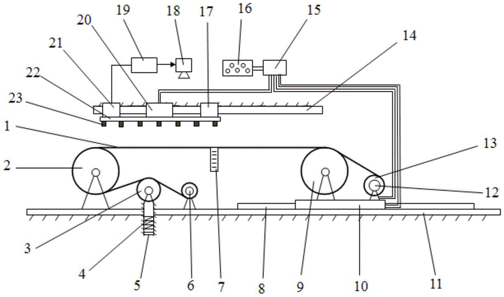
[0026] see figure 1 , the structural form of the axially moving rope lateral vibration measurement system in this embodiment is:

[0027] The wheel train is set, and the wire rope 1 is arranged on the gear train, and the gear train is successively set as the tension pulley 3, the left end guide wheel 2, the right end guide wheel 9 and the reel 13 according to the direction of the wire rope 1 from the end where the wire take-up device 6 is located. The two ends of the wire rope 1 are respectively connected to the wire take-up device 6 and the reel 13; the wire take-up device 6 provides the wire rope recovery force with a coil spring; Displacement scale 7 is set on the long central position; Displacement scale 7 is arranged at the central position of initial rope length, when the initial condition of wire rope lateral vibration is given wire rope center point displacement, the displacement size of this point can be measured, for Numeral Calculations.

[0028] The wire take-up...


PUM


Abstract

The invention discloses a measurement method for a transverse vibration measurement system of an axial movement rope. A middle cord of the system is arranged on a wheel train; a tensioning wheel, a left-end guide wheel, a right-end guide wheel and a reel are arranged on the wheel train along the moving of the cord from the end where an automatic take-up device is arranged in sequence; the two ends of the cord are respectively connected with the take-up device and the reel; the right-end guide wheel and a synchronous motor are fixedly arranged on a mobile platform of a first linear motor; the mobile platform of the first linear motor is supported on a first linear guiderail; the first linear guiderail is fixedly arranged on a rack platform in the movement direction of the cord; a second linear guiderail which is parallel to the first linear guiderail is fixedly arranged right above the cord; a second linear motor is supported on the second linear guiderail; a cross beam is fixedly arranged at the bottom of the second linear motor; displacement sensors are alternately arranged at the bottom of the cross beam. The system is used for the transverse vibration measurement of the axial movement rope, can be used for verifying the result of numerical calculation and can be used as a platform for professional courses teaching and scientific researches.

Description

[0001] This application is a divisional application with an application date of January 25, 2013, an application number of 2013100298374, and the title of the invention is an axially moving rope lateral vibration measurement system and its application. technical field [0002] The invention relates to a measurement method for a test device for measuring the lateral vibration of an axially moving rope at a given moving speed and tension. More specifically, it relates to a testing platform and a testing system for non-contact measurement of lateral displacement and vibration of an axially moving rope under a given initial displacement. Background technique [0003] Axial rope moving system is a type of axial moving system, which has many applications in engineering, such as cable car ropeway, tethered satellite, rope, power transmission belt, magnetic tape, paper tape, etc. The simplified mechanical model of the axial rope moving system can be roughly divided into two categori...

Claims


Application Information

Patent Timeline
Patent Type & Authority Patents(China)
IPC IPC(8): G01H17/00
Inventor 陈恩伟陆益民刘正士王勇吴群曹永友郭耀辉
Owner HEFEI UNIV OF TECH
Learn More