Surface plasma filter based on connection bridge of rectangular ring resonant cavity and incident waveguide

A surface plasmon and resonant cavity technology, applied in instruments, optical filters, optics, etc., can solve problems such as difficult integration, large volume, and change of surface plasmon resonance frequency, and achieve small size, wide application prospects, and simple structure Effect

Inactive Publication Date: 2015-01-07
JIANGNAN UNIV
View PDF5 Cites 10 Cited by
  • Summary
  • Abstract
  • Description
  • Claims
  • Application Information

AI Technical Summary

Problems solved by technology

[0004] As an important integrable photonic device, the surface plasmon filter effectively solves the shortcomings of traditional wave filters such as bulky size and difficulty in integration due to the limitation of the diffraction limit.
Surface plasmon is a coherent resonance formed by an external electromagnetic field and free electrons on the metal surface. The incident light energy is mainly bound on the metal surface and propagates forward. It can effectively overcome the diffraction limit and provide a new way for the development of micro-nano photonic devices. approach, but a small change in the structural parameters of the metal resonator will cause a large change in the surface plasmon resonance frequency

Method used


Image

  • Surface plasma filter based on connection bridge of rectangular ring resonant cavity and incident waveguide
  • Surface plasma filter based on connection bridge of rectangular ring resonant cavity and incident waveguide
  • Surface plasma filter based on connection bridge of rectangular ring resonant cavity and incident waveguide

Examples


Embodiment approach

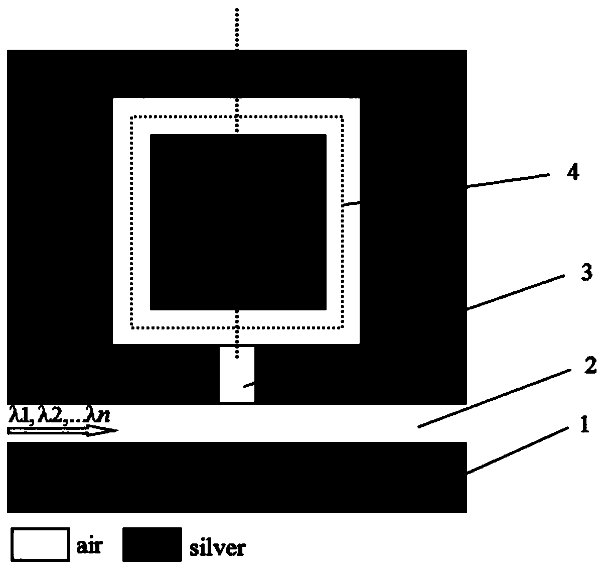
[0016] The present invention is based on the surface plasmon filter of the bridge between the rectangular ring resonant cavity and the incident waveguide, which is mainly composed of metal (silver) layer, main waveguide, waveguide bridge, and rectangular ring resonant cavity. figure 1 . The metal layer (slab) can be produced by using a laser molecular beam crystal epitaxial growth system. The main waveguide, the rectangular ring resonant cavity and the waveguide bridge can be obtained by etching the metal plate by using the focused ion beam etching technology. The optical signal is introduced into the main waveguide through the coupling silicon waveguide or tapered optical fiber, and the optical signal is introduced into the rectangular ring resonant cavity through the waveguide bridge (different bridge lengths introduce different optimal resonance frequencies). When the optical signal is at the optimal resonance wavelength of the cavity lambda i (i=1,2,…), the incident ligh...


PUM


Abstract

The invention provides a surface plasma filter based on a connection bridge of a rectangular ring resonant cavity and an incident waveguide. The means that the resonant frequency of an existing surface plasma filter is adjusted by changing structure parameters is mainly simplified, and thus the purpose for simplifying the manufacturing technology of the filter can be achieved. The surface plasma filter based on the connection bridge of the rectangular ring resonant cavity and the incident waveguide comprises metal layers arranged on the two sides of a dielectric layer, the single rectangular ring resonant cavity is arranged in the metal layer mounted on one side of the dielectric layer, the waveguide bridge is connected between the resonant cavity and the incident waveguide, and the waveguide bridge is arranged on the symmetry axis of the resonant cavity. The structure has an extremely high light constraint effect, the diffraction limit restriction can be broken through, and light can be transmitted on the nanoscale. The surface plasma filter is effectively connected with an electronic device and a traditional photonic device in a matched mode, the waveguide bridge length only needs to be changed, and thus light waves of different wave lengths can be effectively filtered out. The manufacturing technology of the filter is simple, and high application value can be achieved on the aspects of optical communication, optical integration, optical information processing and the like.

Description

technical field [0001] The invention relates to a micro-nano optical device, in particular to a surface plasmon filter based on a bridge between a rectangular ring resonant cavity and an incident waveguide. Background technique [0002] Surface plasmon filters have many advantages, such as simple and compact structure, small size, not limited by the diffraction limit, and provide the possibility of compatibility between electronic circuits and photonic devices, etc., in many fields, especially optical integration, optical computing and optical information processing and other fields, has broad application prospects. [0003] Surface plasmon filters have many unique advantages based on the characteristics of metal nano-rectangular ring resonators and incident waveguide bridge filtering and high beam confinement of metal-dielectric-metal waveguides. Generally speaking, the resonant wavelength of the rectangular ring resonator can be effectively adjusted by rationally designin...

Claims


Application Information

Patent Timeline
Patent Type & Authority Applications(China)
IPC IPC(8): G02B5/20
CPCG02B5/28
Inventor 夏秀山王继成宋慈曲世年
Owner JIANGNAN UNIV
Why Eureka
Try Eureka