Electrode material for thermal-fuse movable electrode

一种温度保险丝、电极材料的技术,应用在电极材料领域,能够解决温度保险丝工作不良等问题,达到实现材料成本、耐熔敷性良好的效果

Active Publication Date: 2015-01-07
TANAKA PRECIOUS METAL IND
View PDF4 Cites 2 Cited by
  • Summary
  • Abstract
  • Description
  • Claims
  • Application Information

AI Technical Summary

Problems solved by technology

This is because the movable electrode is usually energized in a state of contact with the lead wire, and if welding occurs, it will become a major cause of malfunction of the thermal fuse.

Method used


Image

  • Electrode material for thermal-fuse movable electrode
  • Electrode material for thermal-fuse movable electrode
  • Electrode material for thermal-fuse movable electrode

Examples


Embodiment 1

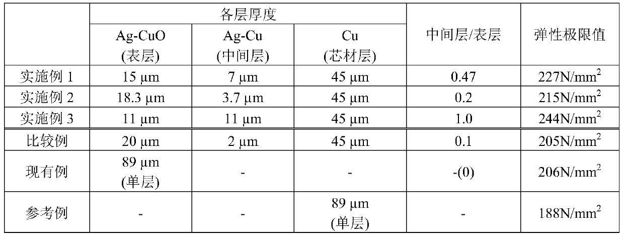
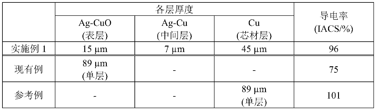
[0034] Example 1 : First, each metal was weighed so that the alloy composition would be Ag: 90.0% by mass and Cu: 10.0% by mass, and an Ag-Cu alloy was melted and cast. Thereafter, the Ag-Cu alloy ingot was rolled to a thickness of 4.15 mm and cut to manufacture an Ag-Cu alloy plate with a width of 115 mm and a length of 195 mm. In addition, an oxygen-free copper ingot was rolled to produce a Cu plate with a width of 120 mm, a length of 200 mm, and a thickness of 9 mm, and the above-mentioned Ag-Cu alloy plate was stacked on both surfaces of the Cu plate, and after cold compression bonding was performed at a pressure of 150 t, In a mixed gas of nitrogen and hydrogen, the temperature was kept at 800° C. for 60 minutes, and then thermocompression bonding was performed at a pressure of 100 tons. The crimped three-layer (Ag-Cu alloy / Cu / Ag-Cu alloy) clad material was rolled to manufacture a clad material strip.

[0035] Next, the clad strip was rolled to 450 μm to form a three-l...

Embodiment 2

[0036] Example 2 : In Example 1, when the inside of the three-layer cladding material (Ag-Cu alloy / Cu / Ag-Cu alloy) was oxidized, the heat treatment time was set to 10 hours. Thus, the thickness of the Ag-CuO alloy layer was set to 91 μm, and the thickness of the Ag-Cu alloy layer was set to 19 μm. Thereafter, calendering was performed in the same manner as in Example 1 to manufacture a five-layer clad material tape. The clad material tape produced was Ag-CuO (18.3 μm) / Ag-Cu (3.7 μm) / Cu (45 μm) / Ag-Cu (3.7 μm) / Ag-CuO (18.3 μm) with a total thickness of 89 μm. The obtained clad material tape was cut and processed to form an electrode material for evaluation.

Embodiment 3

[0037] Example 3 : In Example 1, when the inside of the three-layer cladding material (Ag-Cu alloy / Cu / Ag-Cu alloy) was oxidized, the heat treatment time was set to 3 hours. Thus, the thickness of the Ag-CuO alloy layer was 55 μm, and the thickness of the Ag-Cu alloy layer was 55 μm. Thereafter, calendering was performed in the same manner as in Example 1 to manufacture a five-layer clad material tape. The clad material tape produced was Ag-CuO (11 μm) / Ag-Cu (11 μm) / Cu (45 μm) / Ag-Cu (11 μm) / Ag-CuO (11 μm) with a total thickness of 89 μm. The obtained clad material tape was cut and processed to form an electrode material for evaluation.


PUM


Abstract

The present invention is an electrode material for configuring a thermal-fuse movable electrode, and having a five-layer clad structure comprising a core layer, intermediate layers formed on both surfaces of the core layer, and surface layers formed on the intermediate layers, wherein: the core layer comprises Cu; the intermediate layers comprise an Ag-Cu alloy; the surface layers comprise an Ag-CuO-oxide-dispersion-strengthened alloy; and the ratio of the thickness of the intermediate layers to the thickness of the surface layers (intermediate / surface) is 0.2 to 1.0, inclusive. It is possible to produce this electrode material by sectionally performing an internal oxidation processing on a three-layer clad material obtained by cladding both surfaces of a sheet material comprising Cu with a sheet material comprising an Ag-Cu alloy.

Description

technical field [0001] The present invention relates to electrode materials, in particular to materials suitable for movable electrodes of thermal fuses. Background technique [0002] figure 1 Indicates the structure of a general thermal link. In the thermal fuse 1 , lead wires 21 and 22 are connected to a case 10 made of conductive metal, and an insulating material 30 , springs 41 and 42 , a movable electrode 50 , and a fusible body 60 are housed in the case 10 . The spring 41 is provided between the movable electrode 50 and the insulating material 30 , and the spring 42 is provided between the movable electrode 50 and the meltable body 60 . The movable electrode 50 is in a movable state in contact with the inner surface of the casing 10 . The thermal fuse is normally ( figure 1 state), and electricity is passed from the lead wire 21 to the movable electrode 50 and the case 10 , and further to the lead wire 22 . And, when the thermal fuse becomes overheated due to the ...

Claims


Application Information

Patent Timeline
Patent Type & Authority Applications(China)
IPC IPC(8): H01H37/76C22C5/06C22F1/14C22F1/00
CPCC22C5/06C22F1/14H01H1/0237B32B15/01H01H37/765C22C5/08C22F1/00H01H37/76C22C1/02B32B15/018C22C9/00H01H11/042H01H2011/047H01H85/143
Inventor 坂口理高桥宙也足立信也
Owner TANAKA PRECIOUS METAL IND
Why Eureka
Try Eureka