Intracranial pressure monitor

A monitoring instrument and intracranial pressure technology, applied in intracranial pressure measurement, diagnostic recording/measurement, medical science, etc., can solve problems such as increasing patient pain, difficult wound healing, diagnosis and treatment, prognosis and work efficiency, and guarantees The effect of filling quality, avoiding waste and failure

Active Publication Date: 2015-01-14
LUOHE SHUGUANG HUIZHIKANG BIOTECH
View PDF5 Cites 6 Cited by
  • Summary
  • Abstract
  • Description
  • Claims
  • Application Information

AI Technical Summary

Problems solved by technology

However, although the current automatic control device for external ventricular drainage can also monitor the intracranial pressure, the drainage must be turned off when measuring the intracranial pressure, and the intracranial pressure cannot be measured during the drainage, and the two must be performed separately.
It is self-evident that the risks and

Method used


Image

  • Intracranial pressure monitor
  • Intracranial pressure monitor
  • Intracranial pressure monitor

Examples


Embodiment 1

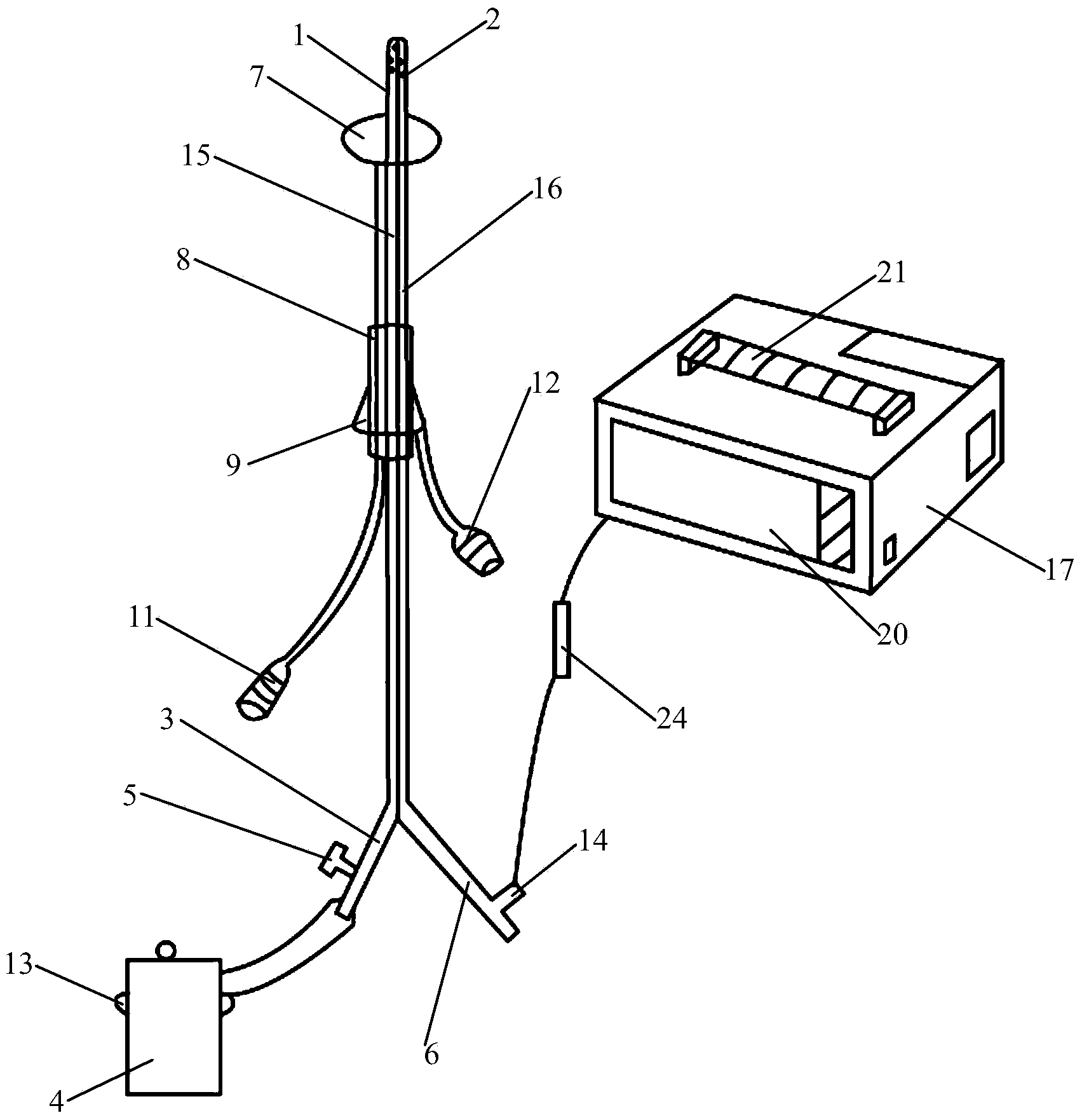
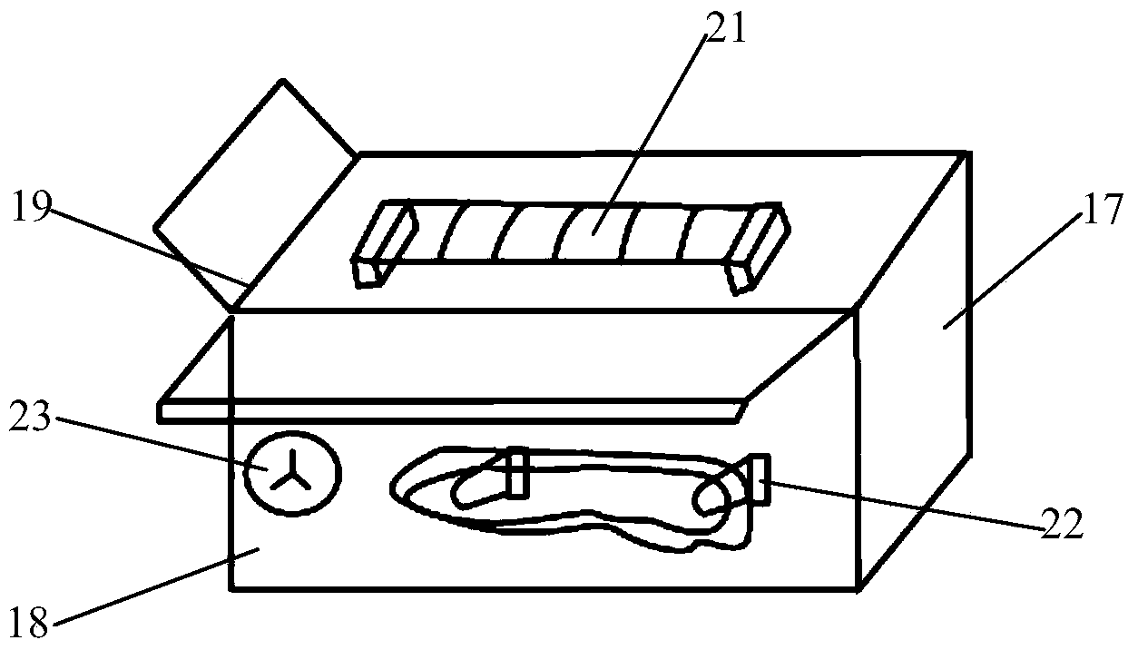
[0024] Embodiment 1: as figure 1 , figure 2 , image 3 As shown, the present invention provides a kind of intracranial pressure monitoring instrument, comprises drainage tube 1 and monitoring display 17, and drainage tube 1 is a long soft catheter, and the drainage end of described drainage tube 1 is provided with drainage hole 2, and its characteristic An inflatable airbag 7 is sheathed near the drainage end of the drainage tube 1, and an inflatable device that can slide along the drainage tube 1 is provided on the outer casing of the drainage tube 1;

[0025] The drainage tube 1 includes a drainage cavity 15 and a pressure measurement cavity 16, the end of the drainage cavity 15 is fixedly connected with the drainage branch joint 3, and the drainage branch joint 3 is connected with the drainage bottle 4, and is set on the drainage branch joint 3 The drainage switch 5, the shape of the drainage tube 1 is Y-shaped, the drainage cavity 15 and the pressure measurement cavity ...

Embodiment 2

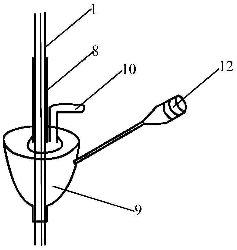
[0034] Embodiment 2: as Figure 4 As shown, the hard upper and lower sliding tube 8 is set on the outer side of the drainage tube 1 jacket, the inflation conduit is located outside the hard upper and lower sliding tube 8, and the branch 14 of the pressure measuring branch pipe joint 6 is arranged on At the junction of the pressure measuring branch pipe joint 6 and the drainage tube 1, the pressure measuring branch pipe joint 6 is a three-way type, which can control the drainage speed to a certain extent, reduce the pain of the patient, and realize continuous and intermittent measurement of intracranial pressure. Others are identical with the structure of embodiment 1.

[0035] Example of use: Place the end of the drainage tube 1 provided with the drainage hole 2 at the perforation of the skull, place the inflatable airbag-7 inside the perforation of the skull, and inflate the inflatable airbag-7 through the spring check valve-11, It is advisable to move the hard up and down s...


PUM


Abstract

The invention belongs to the technical field of brain surgery monitoring instruments, and particularly relates to an intracranial pressure monitor. A drainage hole is formed in the drainage end of a drainage pipe; the drainage pipe is sleeved by an inflation air bag 1 close to the drainage end; a drainage conduit is sleeved by an air inflation device capable of sliding along the drainage pipe; the drainage pipe comprises a drainage cavity and a pressure measuring cavity; the end part of the drainage cavity is fixedly connected with a drainage branch pipe joint; the end part of the pressure measuring cavity is fixedly connected with a pressure measuring branch pipe joint; the pressure measuring branch pipe joint is connected with a detection display through a pressure sensing device; the side surface of the monitoring display is provided with a pressure sensor line box, a power line box and a display screen; and winding lead posts and jacks are respectively arranged in the pressure sensor line box and the power line box. The intracranial pressure monitor is capable of simultaneously carrying out drainage of cerebrospinal fluid and measurement of intracranial pressure, realizing real-time monitoring, saving time for rescue; in addition, infection is not easily caused due to a plurality of openings, the intracranial pressure monitor does not easily fall off from the openings, and the pain of a patient is relieved.

Description

technical field [0001] The invention belongs to the technical field of brain surgery monitoring instruments, in particular to an intracranial pressure monitoring instrument. Background technique [0002] External ventricular drainage is a common technique in neurosurgery. It is an important method to rescue severe diseases such as intracranial hypertension, brain trauma, cerebral edema, cerebral hemorrhage, obstructive hydrocephalus, etc. The purpose of external ventricular drainage is to effectively drain out the ventricle. Reduce intracranial pressure, reduce cerebral edema, avoid or reduce the onset of cerebral vasospasm, reduce brain function damage, and improve the clinical symptoms of patients. Continuous and uninterrupted monitoring of intracranial pressure (ICP) can observe the dynamic changes of intracranial pressure, guide diagnosis, treatment, prognosis and adjust drainage speed at any time. However, although the current automatic control device for external vent...

Claims


Application Information

Patent Timeline
IPC IPC(8): A61B5/03A61M1/00
CPCA61B5/031A61M25/0023A61M25/1025A61M31/002A61M2025/0003A61M2025/0037A61M2025/1015
Inventor 万鹏付正英韩如泉
Owner LUOHE SHUGUANG HUIZHIKANG BIOTECH
Why Eureka
Try Eureka