Oil tube hydraulic lifting device and application method

A lifting device and tubing technology, which is applied in the direction of drill pipe, casing, earthwork drilling, etc., can solve the problems of low work efficiency, poor personnel safety, and high labor intensity of workers, so as to reduce labor intensity, ensure safe production, The effect of improving the status quo of work

Active Publication Date: 2015-01-14
PETROCHINA CO LTD
View PDF6 Cites 7 Cited by
  • Summary
  • Abstract
  • Description
  • Claims
  • Application Information

AI Technical Summary

Problems solved by technology

There are factors such as high labor intensity, low work efficiency, and poor personnel safety for the workers at the post

Method used


Image

  • Oil tube hydraulic lifting device and application method

Examples


Embodiment Construction

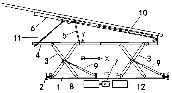
[0017] An oil pipe hydraulic lifting device mainly consists of three parts: a machine body, a hydraulic system and a control system.

[0018] The machine body includes five components including machine base 1, machine base legs 2, cross-shear support 3, lifting platform 4, diagonal brace 5, and telescopic slideway 6; the hydraulic system includes hydraulic pump station 7, control valve 8, and lifting cylinder 9. It is composed of telescopic oil cylinder 10 and inclined extension oil cylinder 11; the control system is composed of power control cabinet 12 and so on.

[0019] combined with figure 1 The structural schematic diagram of the oil pipe hydraulic lifting device further describes the present invention in detail.

[0020] It is mainly composed of three parts: body, hydraulic system and control system. The machine body includes five components including machine base 1, machine base legs 2, cross-shear support 3, lifting platform 4, diagonal brace 5, and telescopic slidew...


PUM


Abstract

The invention discloses an oil tube hydraulic lifting device and an application method. The oil tube hydraulic lifting device is mainly formed by a machine body, a hydraulic system and a control system; the machine body comprises an engine base, engine base supporting legs, cross shear supports, a lifting platform, an inclined support and an extensible sliding channel; the hydraulic system comprises a hydraulic pump station, a control valve, a lifting oil cylinder, an extensible oil cylinder and an inclined extension oil cylinder; the control system is formed by a power source control cabinet and the like. The oil tube hydraulic lifting device is characterized in that a hydraulic device lifts and conveys a tube rod to an assigned working position through a mechanical mechanism, and meanwhile, a working table can be served as a tube rod movement sliding channel and directly receives and sends the tube rod during a lifting process; works of manual oil tube lifting and back and forth oil tube receiving and sending are replaced, the labor intensity of workers is reduced, and safety production is guaranteed.

Description

technical field [0001] The invention relates to oil field workover auxiliary machinery, in particular to a oil pipe hydraulic lifting device and a use method for well workover operation. Background technique [0002] At present, in oilfield workover operations, the wellhead operation platform is very high from the ground due to the installation of wellhead devices such as wellhead devices, and the pulling and supply of tubing during tripping operations is completely completed by manpower and the suspension system of the workover rig . There are factors such as high labor intensity of post workers, low work efficiency, and poor personnel safety. It is the need for the development of downhole operations in oilfields to replace manpower with machinery, improve the dirty and tiring working conditions of current operators, and ensure safe production. Contents of the invention [0003] The purpose of the present invention is: [0004] Provide a kind of oil pipe hydraulic lift...

Claims


Application Information

Patent Timeline
IPC IPC(8): E21B19/00
CPCE21B19/00
Inventor 奎万仓叶光辉陈微熙王进库虎元林焦士杰蔡有山冯振
Owner PETROCHINA CO LTD
Why Eureka
Try Eureka