Digital helmet display device tracking system of visual-aided inertial measuring unit

A technology of inertial measurement unit and digital helmet, which is applied in helmets, offensive equipment, measuring devices, etc., can solve the problems of inability to meet accuracy requirements, slow processing speed, and large computing space occupied by visual images

Inactive Publication Date: 2015-01-14
HARBIN DIANSHI SIMULATION SCI & TECH
View PDF5 Cites 20 Cited by
  • Summary
  • Abstract
  • Description
  • Claims
  • Application Information

AI Technical Summary

Problems solved by technology

[0003] The helmet tracking system has been used in the helmet sight for a long time. The traditional sighting methods are mainly electromechanical, electromagnetic and photoelectric: the electromechanical is to connect the helmet with the top of the cockpit through a connecting rod device and an electromagnetic clutch. The goniometer at both ends of the connecting rod measures the angle of head rotation; the electromagnetic type uses the magnetic sensor and magnetic radiator in the helmet and cockpit to obtain the angle of the head relative to the positive direction of the fuselage by using the deviation of the magnetic field direction. The installation will make the pilot's head load heavy, and it is easy to cause electromagnetic interference to other equipment in the cabin; the photoelectric type uses the infrared receiver in the cockpit to receive the infrared signals from the infrared diodes on both sides of the helmet, and compares it with the reference signal. Calculating the angle of head rotation, although this method is more advanced and improves some of the shortcomings of the first two methods, but the structure of the photoelectric aiming system is complex, it is difficult to install and debug, and it also causes some inconvenience to the use of helmet sights
[0004] With the development of computer vision, more and more scholars turn their attention to visual measurement, and its application value for helmet sights is gradually reflected. Due to its low cost, light weight, high reliability, convenient use, and The advantages of mature technology greatly reduce the burden on pilots and the difficulty of installation and debugging. Therefore, many scholars have carried out a lot of simulation and research on helmet sights based on visual measurement and image processing technology, but the processing of visual images requires a lot of time. Computational space, the processing speed is relatively slow. To meet the fast and real-time line-of-sight alignment, the onboard computer must have a large storage space and high computing efficiency
[0005] Based on inertial measurement technology, the inertial measurement unit is a very mature measurement method and has been widely used in various aircraft and ships. It is a completely autonomous and real-time measurement and navigation method, but the measurement error of the inertial measurement unit accumulates with time, and coupled with its own drift characteristics, it cannot meet the long-term accuracy. Requirements, the method of the present invention is based on the method of visual aided inertial measurement unit, utilizes mature inertial measurement unit measurement technology, adds the assistance of visual measurement, corrects the error of inertial measurement with certain time interval, in order to achieve the purpose of accurate tracking helmet posture

Method used


Image

  • Digital helmet display device tracking system of visual-aided inertial measuring unit
  • Digital helmet display device tracking system of visual-aided inertial measuring unit
  • Digital helmet display device tracking system of visual-aided inertial measuring unit

Examples


specific Embodiment approach

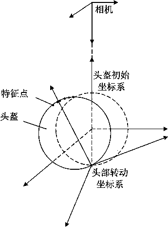
[0122] Specific embodiments, this implementation method combines Figure 1 to Figure 3 To give a detailed introduction to the present invention, the five coordinate systems used in the present invention are such as figure 1 Shown.

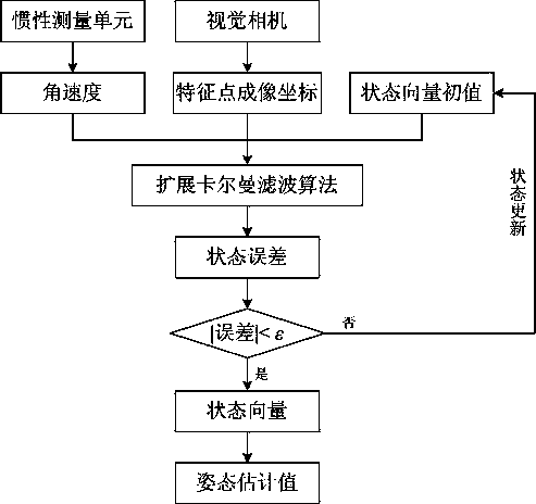
[0123] The method of the present invention is a measurement method of a visual-assisted inertial measurement unit. This method is based on inertial measurement and assisted by visual measurement. The correction method of visual measurement is to correct the inertial measurement error once every fixed time. The algorithm flow of the present invention is as follows figure 2 Shown.

[0124] First, set the initial parameters of the system, including system equipment parameters (such as the initial position of the helmet, the size of the helmet, the number of characteristic points on the top of the helmet and the coordinates in the head rotation coordinate system, the specific parameters and specific positions of the camera, etc. ) And the initial parameter...


PUM


Abstract

The invention discloses a digital helmet tracking system based on a visual-aided inertial measuring unit, which integrates the advantages of an inertial measuring unit and the advantages of vision measurement to autonomously realize the tracking of a helmet posture in real time. The digital helmet display device tracking system is characterized in that the error of the inertial measurement accumulated along with the time can be corrected by utilizing the visual aiding method, so that the posture and position of a digital helmet display device can be tracked and calculated in real time. The noise effect in the measuring process is considered in the method, and the helmet posture is estimated by utilizing a Kalman filter algorithm, so that the affection of the noise on the measuring result is reduced as far as possible. The digital helmet display device tracking system has the advantages of good autonomy, good real-time property, small calculation amount, low cost, light weight, small load, convenience in use, high precision and the like.

Description

Technical field [0001] The invention is related to computer vision and inertial measurement, and belongs to the field of visual measurement and integrated navigation research. The helmet-mounted display tracking system established has the characteristics of light weight, comfort, fast response, high precision, etc., and a visual assisted inertial measurement unit is adopted. The navigation method can accurately track the attitude of the helmet in real time and reliably. Background technique [0002] The helmet tracking system realizes the aiming of the weapon system by tracking the pilot's head movement. In actual flight tasks, the pilot not only needs to check the instrument panel data changes at all times, but also pay attention to the position of the target outside the cabin, and aim at the target through the pilot. The method of changing the direction of sight to control the aiming system to aim at the target is very meaningful. The direction of the pilot’s sight is reflected...

Claims


Application Information

Patent Timeline
Patent Type & Authority Applications(China)
IPC IPC(8): G01C19/00G01P15/00A42B3/04F41G11/00
CPCG01C21/165A42B3/0406G01C11/00G01C25/005
Inventor 张泽旭刘蕾郑博
Owner HARBIN DIANSHI SIMULATION SCI & TECH
Why Eureka
Try Eureka