Single-frame type impeller of wind turbine

A wind-driven generator and single-frame technology, applied to wind-driven engines, wind-driven engines consistent with the wind direction, wind-driven engine control, etc., can solve the problems of long cost recovery period, increased sway, and friction loss between steel ropes and frame grooves Large and other problems, to achieve the effect of improving wind energy utilization efficiency, increasing output power, and facilitating daily maintenance

Active Publication Date: 2015-01-21
清新能源科技张家口有限公司
View PDF8 Cites 21 Cited by
  • Summary
  • Abstract
  • Description
  • Claims
  • Application Information

AI Technical Summary

Problems solved by technology

[0003] At present, most wind turbines are in the form of three driving blades with the main shaft horizontally arranged. Fans with this structure usually rely on increasing the length of the blades, that is, increasing the sweeping area of ​​the blades and increasing the rated output power. Therefore, while increasing the power of the fan, its The overall volume, height, and weight also increase accordingly. The higher body height increases the overall shaking, resulting in a decrease in wind resistance, and greatly increases the design requirements for the structure, strength, and materials of the entire machine, especially the blade angle adjustment mechanism. It is complicated, and the angle adjustment of each blade is asynchronous, which increases the cost of production, operation and daily maintenance. At the same time, it makes the fan more sensitive to the wind speed, and the available range of wind speed is narrowed (when the wind speed is greater than 25m / s, it is generally shut down to avoid danger), Causes a lot of waste of wind power resources, the cost of obtaining unit kilowatts of electric energy rises, and there are generally problems of large investment in wind power equipment, long cost recovery cycle, and low annual utilization hours
However, civil wind turbines are limited by their cost and structure, the angle of the blades cannot be adjusted, and the failure of the wind wheel to overspeed and "speeding" is common.
In addition, the fan blades of this structure are limited by materials and structures. During operation, especially in thunderstorm weather, the probability of breaking the blades due to lightning strikes is high.
[0004] In addition, patent No. ZL 201420077847.5 discloses a horizontal-axis wind turbine with door-shaped blades and a retractable wind rotor, and ZL 201420078001.3 discloses a horizontal-axis wind turbine with paddle-shaped blades and a drum-shaped retractable wind rotor. It solves the problems of blade synchronization and fan size reduction, but because the wind wheel structure is two to three circular frames and multiple support rods, the weight of the head part of the whole machine has not been reduced, especially the adjustment mechanism of the blades. Using the method of setting grooves on the frame and pulling them with steel ropes, the structure is complex, corrosion resistance, daily maintenance, and repairs are difficult, and the friction loss between the steel ropes and the frame grooves is relatively large, resulting in unsatisfactory overall operation and unit power generation costs

Method used


Image

  • Single-frame type impeller of wind turbine
  • Single-frame type impeller of wind turbine
  • Single-frame type impeller of wind turbine

Examples


Embodiment 1

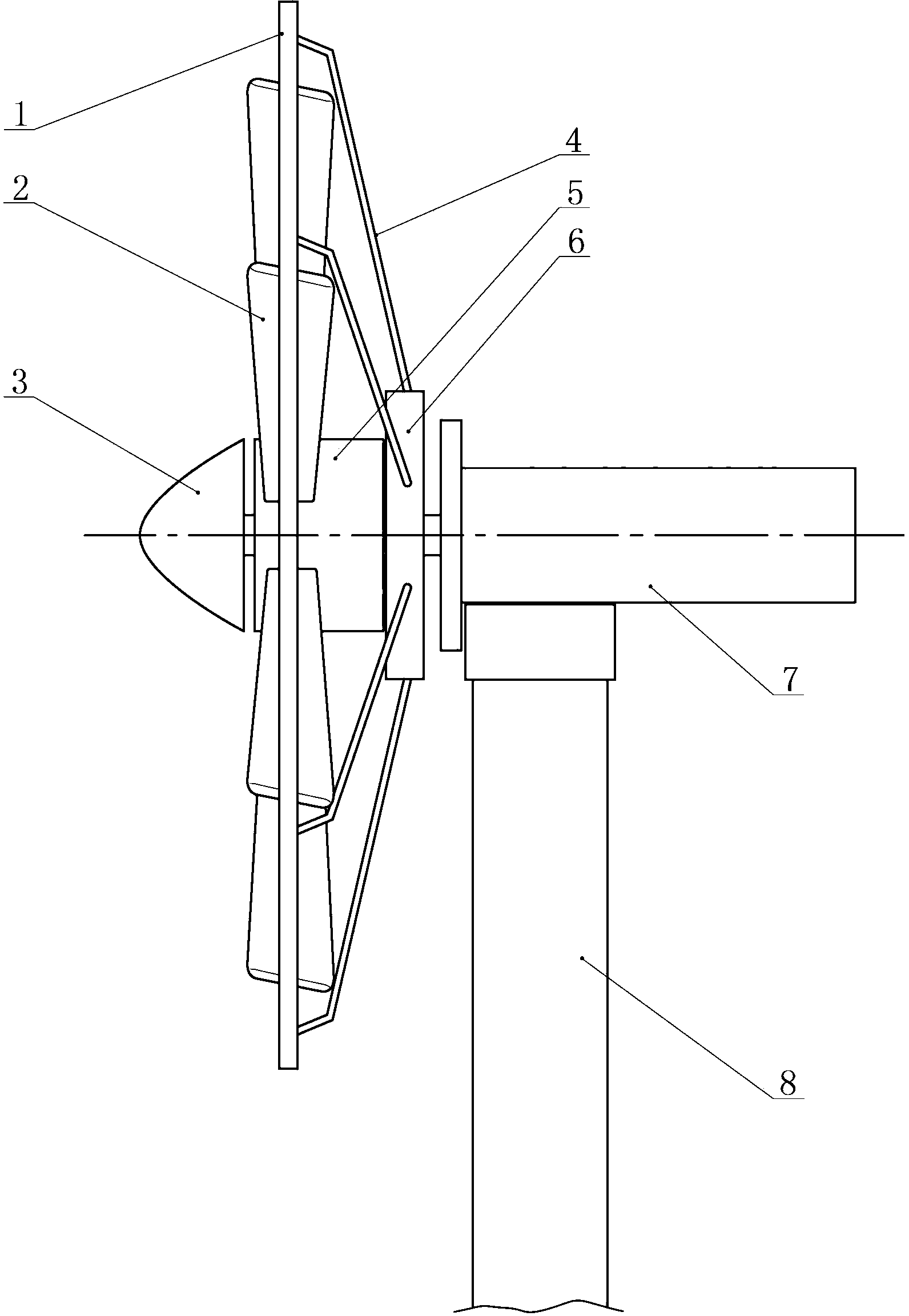
[0026] Depend on Figure 1 ~ Figure 4 It can be seen that the technical solution of the present invention includes the generator 7, the wind rotor frame 1, the blade 2, the support seat 6, the inclined support rod 4, and the blade adjustment device with the main shaft horizontally arranged; the generator 7 is assembled on the top of the pole tower 8;

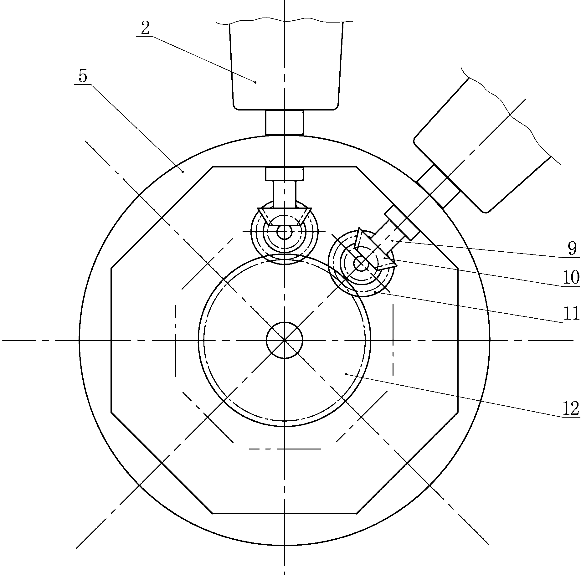
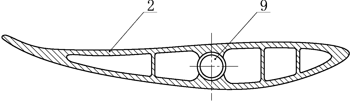
[0027] The blade adjustment device includes a blade adjustment chamber 5, a power unit, and an adjustment mechanism; the blade adjustment chamber 5 is horizontally cylindrical, and the rear end of the blade adjustment chamber 5 is connected and fixed on the front of the support seat 6, and the blade adjustment chamber 5 and the support seat 6 are integrated. , assembled at the front end of the main shaft of the generator, and rotates with the main shaft; the supporting base 6 is connected with the wind rotor frame 1 through the inclined support rod 4, so that the blade adjustment chamber 5 is located in the center of the wind rot...

Embodiment 2

[0032] In this embodiment, a large-scale wind generator with a larger output power is taken as an example, and the Figure 5 ~ Figure 7It can be seen that the difference between this embodiment and Embodiment 1 is that due to the large volume and weight of the fan, three spoke-type poles 13 are connected and fixed between the blade adjustment chamber 5 and the wind wheel frame 1. The shape of "" is evenly distributed to enhance the strength and wind resistance of the wind wheel; the adjustment mechanism of the blade adjustment device adopts a link-type adjustment mechanism, which includes a push-pull transmission mechanism, an adjustment frame 19, a rotating arm 20, and a connecting rod 21 The push-pull transmission mechanism is composed of swing arm 16, positioning shaft 15, main drive arm 17, and push-pull rod 18; the inner side of the blade adjustment chamber 5 cylindrical side walls is provided with a circle of annular guide rails, and the adjustment frame 19 is assembled o...


PUM


Abstract

The invention relates to the technical field of wind power generation equipment, in particular to a single-frame type impeller of a wind turbine. An existing horizontal-axis wind turbine affected by the structure and materials is low in wind utilization rate, high in design requirements, heavy and large, difficult to maintain and easy to overspeed and gallop. The single-frame type impeller of the wind turbine comprises a wind wheel frame, a vane adjusting device, a support and diagonal support rods, wherein the vane adjusting device is connected with the support and assembled at the front end of a turbine spindle, the wind wheel frame is connected with the support via the diagonal support rods, and vanes are assembled in the wind wheel frame and around the vane adjusting device via shafts, the vane adjusting device is provided with a closed adjusting chamber, and a gear type or connecting rod type adjusting mechanism is assembled in the adjusting chamber. By changing the vane connecting mode, the number of the vanes is increased, wind energy utilization efficiency is improved, output power of the wind turbine is increased, volume, height and weight of the wind turbine are reduced, and the single-frame type impeller is reasonable in structure and convenient for daily maintenance and overhauling.

Description

technical field [0001] The invention relates to the technical field of wind power generating equipment, in particular to a single-frame impeller of a wind power generator. Background technique [0002] Wind power generators use natural wind energy to drive the blades and the main shaft of the generator to rotate, and drive the rotor of the motor to rotate to generate electricity. It has the characteristics of environmental protection and has been widely used. [0003] At present, most wind turbines are in the form of three driving blades with the main shaft horizontally arranged. Fans with this structure usually rely on increasing the length of the blades, that is, increasing the sweeping area of ​​the blades and increasing the rated output power. Therefore, while increasing the power of the fan, its The overall volume, height, and weight also increase accordingly. The higher body height increases the overall shaking, resulting in a decrease in wind resistance, and greatly i...

Claims


Application Information

Patent Timeline
Patent Type & Authority Applications(China)
IPC IPC(8): F03D1/06F03D7/04
CPCF03D1/06F03D1/0608F03D7/04F03D1/04F05B2240/2211F05B2260/79Y02B10/30Y02E10/72F03D1/0658
Inventor 张旭阳张导宇王星涛贾雪姣刘宁杨飞韩艳洁张效新白振义
Owner 清新能源科技张家口有限公司
Why Eureka
Try Eureka