Membrane gas meter sampling and counting mechanism

A membrane gas meter and counting mechanism technology, which is applied to volume measurement, measuring devices, instruments, etc., can solve the problems of weak anti-magnetic interference ability and miscount hidden dangers, and achieve good anti-jitter, accurate sampling and counting, and reduce production costs. Effect

Active Publication Date: 2017-12-05
GOLDCARD HIGH TECH
View PDF1 Cites 0 Cited by
  • Summary
  • Abstract
  • Description
  • Claims
  • Application Information

AI Technical Summary

Problems solved by technology

[0003] In order to solve the technical problems of weak anti-magnetic interference ability and hidden danger of miscounting in the sampling and counting device of the membrane gas meter in the prior art, the present invention provides a sampling device for membrane gas meter measurement that meets the anti-shake and anti-magnet attack simple production process. counting mechanism

Method used


Image

  • Membrane gas meter sampling and counting mechanism
  • Membrane gas meter sampling and counting mechanism
  • Membrane gas meter sampling and counting mechanism

Examples


Embodiment 1

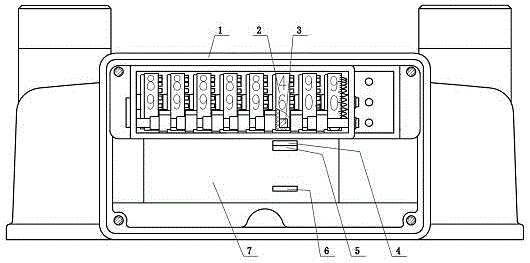
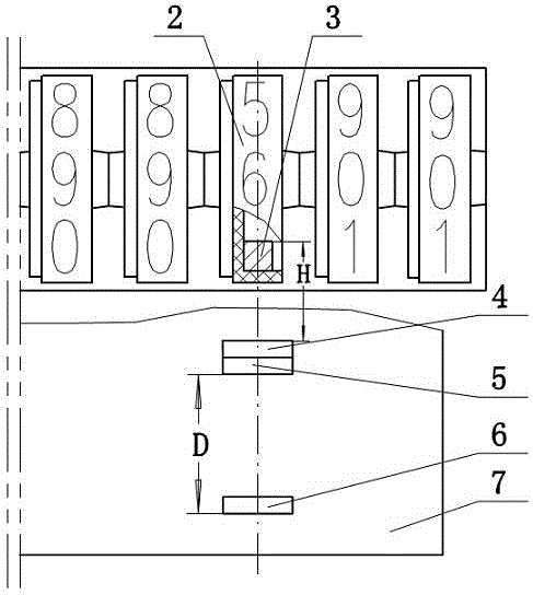
[0018] Such as figure 1 with 2 As shown, a membrane gas meter sampling and counting mechanism includes a gas meter upper casing 1, a character wheel assembly installed in the gas meter upper casing 1, and a control circuit board 7 arranged below the character wheel assembly. The character wheel assembly has eight number wheels 2 coaxially connected in series, and the third one from the right end is the ones digit wheel. The number wheels 2 in the embodiment of this specification are all described with the ones digit wheel as an example. The number wheel 2 is provided with several magnetic steels 3 . The control circuit board 7 is provided with a sampling sensor I4 and a sampling sensor II5. The sampling sensor I4 and the sampling sensor II5 are Hall elements, and the two sampling sensors are close to each other and arranged in the diameter direction of the digital wheel 2 . In order to meet the anti-shake, there is a certain difference in the sensitivity of the two sampling...

Embodiment 2

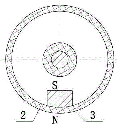
[0023] Figure 4 A schematic diagram of installing two magnets 3 for the number wheel 2. The two magnets 3 are symmetrically distributed with the central axis of the number wheel 2 as the axis of symmetry. The N pole of one magnetic steel 3 is connected with the rim of the number wheel 2, and the S pole of the other magnetic steel 3 is connected with the rim of the number wheel 2. The rotation of the digital wheel 2 drives the rotation of the magnetic steel 3, and the rotation of the magnetic steel 3 for one revolution is as follows:

[0024] output port

Embodiment 3

[0026] Figure 5 Schematic diagram of installing four magnets 3 for the number wheel 2. Four magnetic steels 3 are evenly distributed along the rim of the number wheel 2. Two magnetic steels 3 distributed symmetrically with the axis of the digital wheel 2 as a symmetrical axis form a group. In the vertical group, the N pole of each magnetic steel 3 is connected to the rim of the digital wheel 2. In the horizontal group, The S pole of each magnetic steel 3 is connected with the rim of the number wheel 2 . The digital wheel 2 drives the magnetic steel 3 to rotate, and the magnetic steel 3 rotates once. The sampling sensor Ⅰ4 and the sampling sensor Ⅱ5 sense the output pulse generation timing table as follows:

[0027]

[0028]


PUM


Abstract

The invention provides a membrane gas meter sampling and counting mechanism, which relates to the technical field of gas meters. It includes the upper casing of the gas meter, the character wheel assembly and the control circuit board. The number wheel of the character wheel assembly is provided with several magnets, and the control circuit board is provided with sampling sensor Ⅰ and sampling sensor Ⅱ. The sampling sensor Ⅰ and sampling sensor Ⅱ are close to each other. , and is located in the diameter direction of the number wheel. The invention solves the technical problems of the gas meter sampling and counting device in the prior art, which have weak anti-magnetic interference capability and hidden dangers of miscounting. The beneficial effect of the present invention is that the counting signal is directly collected by the control circuit board, eliminating intermediate links, eliminating hidden dangers affecting the accuracy of sampling and counting, and saving raw materials. The magnetic sensing element and the control circuit board are directly welded, which is suitable for the SMT chip technology, and the welding reliability is good, the process is simple, the production cost is reduced, and the production efficiency is improved. The anti-shake and anti-external magnetic field attack effects are good, ensuring accurate sampling and counting.

Description

technical field [0001] The invention relates to the technical field of gas meters, in particular to a sampling and counting mechanism for membrane gas meter measurement. Background technique [0002] With the rapid development of the gas industry, piped gas has been widely used as fuel in cities in our country. The sampling and counting methods of membrane gas meters on the market today are mostly realized by magnetic steel with sensors. The principle of the sampling and counting method is basically: the magnetic steel is fixed on the counter wheel, and the reed switch or Hall element is welded on the sampling printed circuit board as a sensor and fixed on both sides of the counter wheel. The sensor relies on the strength of the magnetic force of the magnetic steel to generate a state of attraction or disconnection, and the on-off signal is transmitted to the master control unit on the control board through the lead wire for counting. China patent authorization announcemen...

Claims


Application Information

Patent Timeline
Patent Type & Authority Patents(China)
IPC IPC(8): G01F15/07
Inventor 贾伟
Owner GOLDCARD HIGH TECH
Why Eureka
Try Eureka