Optical fiber vibration detection device and method

A fiber optic vibration and detection device technology, applied in measuring devices, measuring ultrasonic/sonic/infrasonic waves, instruments, etc., can solve the problems of high cost, complex structure, short sensing distance, etc., and achieve simple structure, accurate sensing results, low cost effect

Inactive Publication Date: 2015-01-21
SHENZHEN ARISTONE TECH CO LTD
View PDF6 Cites 0 Cited by
  • Summary
  • Abstract
  • Description
  • Claims
  • Application Information

AI Technical Summary

Problems solved by technology

However, the transmission distance of optical fibers in such systems is limited by spontaneous emission and harmful nonlinear effects, and ordinary optical fiber sensing systems usually have short sensing distances
However, increasing the sensing distance of the fiber optic sensing system through cascade amplification is complex and expensive
Therefore, the sensing distance of the existing optical fiber sensing system is limited by the output power of the optical fiber, and inaccurate sensing results are prone to occur in systems formed by laying optical fibers over long distances

Method used


Image

  • Optical fiber vibration detection device and method
  • Optical fiber vibration detection device and method
  • Optical fiber vibration detection device and method

Examples


Embodiment Construction

[0040] In order to describe the technical content, structural features, objectives and effects of the present invention in detail, the present invention will be described in detail below in conjunction with the accompanying drawings and embodiments.

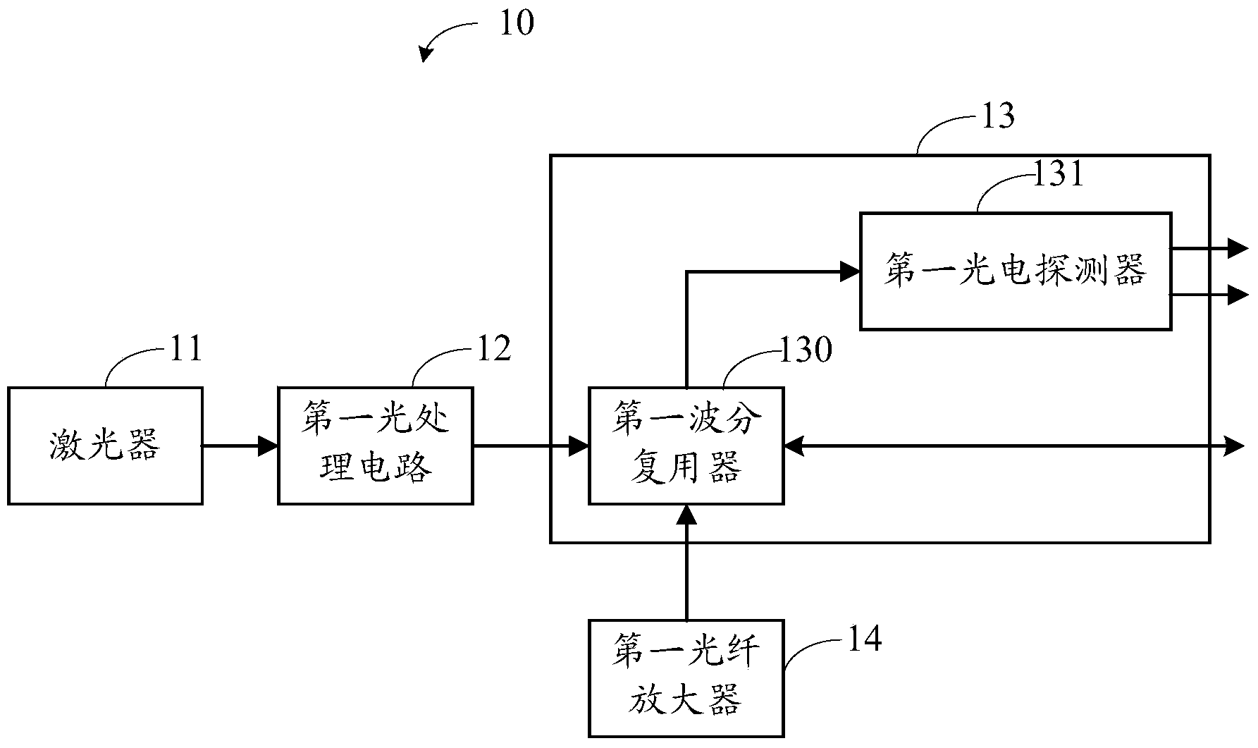
[0041] see figure 1 , is a schematic structural view of the first embodiment of an optical fiber vibration detection device of the present invention. The device 10 includes a laser 11 , a first optical processing circuit 12 , a second optical processing circuit 13 and a first optical fiber amplifier 14 .

[0042] The laser 11 is used to emit laser light to generate a light source signal.

[0043] The first light processing circuit 12 is used for modulating and amplifying the light source signal.

[0044] The second optical processing circuit 13 includes a first wavelength division multiplexer 130 and a first photodetector (APD) 131 . Wherein, the first wavelength division multiplexer 130 is used to obtain the light source sign...


PUM


Abstract

The invention discloses an optical fiber vibration detection device and method. The device comprises a laser device, a first optical processing circuit, a second optical processing circuit and a first optical fiber amplifier. The first optical processing circuit modulates and amplifies light source signals generated by the laser device, a first wavelength division multiplexer of the second optical processing circuit obtains the light source signals modulated and amplified by the first optical processing circuit, and the first optical fiber amplifier amplifies the light source signals obtained by the first wavelength division multiplexer, so the first wavelength division multiplexer transmits the light signals amplified by the first optical fiber amplifier to the outside of the optical fiber vibration detection device and receives light signals returned from the outside of the optical fiber vibration detection device. A first photoelectric detector of the second optical processing circuit converts the returned light source signals and outputs corresponding analog signals. Thus, the optical fiber vibration detection device and method can improve optical fiber output power so that a sensing distance can be increased, and a sensing result is relatively accurate.

Description

technical field [0001] The invention relates to the technical field of optical fiber sensing, in particular to an optical fiber vibration detection device and method. Background technique [0002] The existing optical fiber sensing system acts on the external disturbance signal on the optical fiber. According to the photoelastic effect, it causes the phase change of the transmitted light in the optical fiber. Through the interference method, two interference light interference signals containing external disturbance information are obtained. The interference signal is processed by photoelectric conversion, amplification, A / D conversion, etc., and a digital signal containing external disturbance information is obtained. Usually, a server is set up on the monitoring side to process the obtained optical interference signal, digital signal, etc., so as to realize the detection of the optical fiber sensing vibration source. However, the transmission distance of optical fibers in...

Claims


Application Information

Patent Timeline
IPC IPC(8): G01H9/00
Inventor 刘博宇秦长伟曲洪权
Owner SHENZHEN ARISTONE TECH CO LTD
Why Eureka
Try Eureka