Phase-change heat exchange pipe bundle with optimized structure and production process of phase-change heat exchange pipe bundle

A technology of phase-change heat transfer and optimized structure, which is applied to indirect heat exchangers, household heating, heating methods, etc., can solve the problems of low installation efficiency and obstacles to the large-scale promotion of air-source heat pump direct expansion heat transfer technology, and achieve Improvement of construction speed, improvement of energy utilization rate, and improvement of energy efficiency ratio

Inactive Publication Date: 2015-01-28
陈万仁
View PDF6 Cites 6 Cited by
  • Summary
  • Abstract
  • Description
  • Claims
  • Application Information

AI Technical Summary

Problems solved by technology

The tube bundle solution provided by the patented technology of the patent application number ZL2012202753539: after the on-site installation is completed, the effect is better, and it also solves some processing and transportation problems, and solves the factory welding and on-site laying of the capillary network. However, the application practice of this tube bundle product shows that : Whether it is factory manufacturing or construction site installation efficiency is still very low, which hinders the large-scale promotion of air source heat pump direct expansion heat transfer technology

Method used


Image

  • Phase-change heat exchange pipe bundle with optimized structure and production process of phase-change heat exchange pipe bundle
  • Phase-change heat exchange pipe bundle with optimized structure and production process of phase-change heat exchange pipe bundle
  • Phase-change heat exchange pipe bundle with optimized structure and production process of phase-change heat exchange pipe bundle

Examples


Embodiment 1

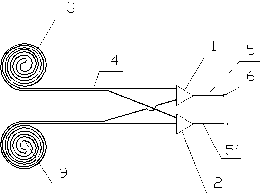
[0026] Embodiment 1: as figure 1 As shown, a phase-change heat tube bundle with an optimized structure is used to extract the phase-change heat of compressed steam for phase-change heat, including two capillary tubes 4 , a gas distributor 1 and a liquid return head 2 . Each capillary is wound into a capillary disk 3 .

[0027] The capillary coil is formed by a single capillary 4 having a bend 9 in the middle of the length direction, and then winding side by side after bending. There are two joints left on each capillary disc. The joints at both ends of the capillary 4 are respectively welded on the gas distributor 1 and the liquid return head 2. The connected liquid return joint 5', the ends of the air inlet joint 5 and the liquid return joint 5' are all provided with a nanocap 6 for connection.

[0028] How to use: After welding multiple capillaries in the tube bundle in the ZL2012202753539 patent technology to the gas distributor or liquid return head, the overall processi...

Embodiment 2

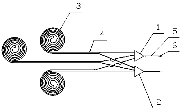
[0029] Embodiment 2: as figure 2 As shown, a phase-change heat pipe bundle with an optimized structure includes three capillaries 4 , a gas distribution head 1 and a liquid return head 2 . After bending, at least five helical concentric circles with different diameters are wound side by side.

[0030] Other structures are the same as in Embodiment 1.

Embodiment 3

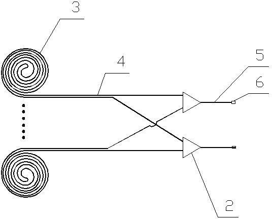
[0031] Embodiment 3: as image 3 As shown, a phase-change heat pipe bundle with an optimized structure includes a plurality of capillaries 4 , a gas distribution head 1 and a liquid return head 2 . The inner diameter of the capillary is 1.0mm~6mm, and the length is 3m~46m. The number of capillaries in each group of tube bundles is 4-50.

[0032] Other structures are the same as in Embodiment 1.


PUM


Abstract

The invention discloses a production process of a phase-change heat exchange pipe bundle with an optimized structure. The production process includes that each single capillary pipe is bent from the middle of the length direction, and bending diameter is not smaller than four times of diameter of each capillary pipe; two parallel capillary pipes are formed after bending and wound to form a capillary pipe disc; each capillary pipe disc formed by the corresponding single capillary pipe is bundled by using a bundling wire; two joints set apart by each capillary pipe disc are welded on an air distributing head and a liquid returning head respectively. The production process is an extension of patented technology ZL2012202753539, aims to overcome the defects of the patented technology and improve the production process and is an optimized improvement on the patented technology. By adopting the production process to manufacture a pipe bundle coiler, automatic welding can be realized, manufacturing speed of a factory can be increased by more than five times, and speed of an on-site construction laying link can be increased by more than five times.

Description

technical field [0001] The invention belongs to an auxiliary device of heat exchange equipment, and in particular relates to a tube bundle of a heating and cooling device for phase change heat extraction by extracting the phase change heat of compressed steam and its production process. Background technique [0002] At present, with the rapid development of scientific and technological innovation and manufacturing technology, in the field of heat pump compressors, frequency conversion and digital scroll compressors have come out, liquid spray cooling technology, low-temperature condensation technology, etc. It can operate stably at low temperature and has a high operating energy efficiency ratio, which opens up a new way for the use of air source heat pumps in the heating field. In recent years, people have adopted large-scale water source heat pump systems to solve heating and cooling problems. However, due to the limitation of geological conditions in most areas of my coun...

Claims


Application Information

Patent Timeline
Patent Type & Authority Applications(China)
IPC IPC(8): F28D15/04F24D19/00F25B39/00
Inventor 梁年良陈万仁牛保奎孙长江何欣刘鹏
Owner 陈万仁
Why Eureka
Try Eureka