[0021] The specific embodiments of the present invention will be described in further detail below in conjunction with the drawings and embodiments. The following examples are used to illustrate the present invention, but not to limit the scope of the present invention.
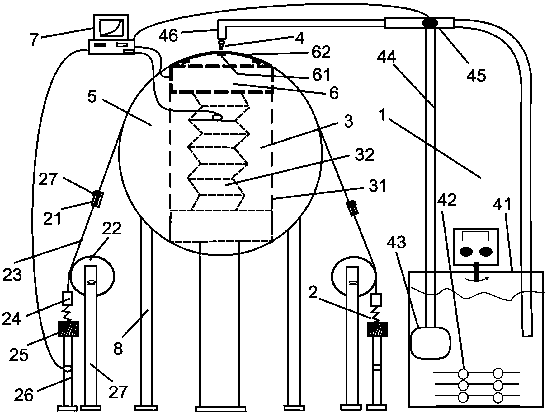
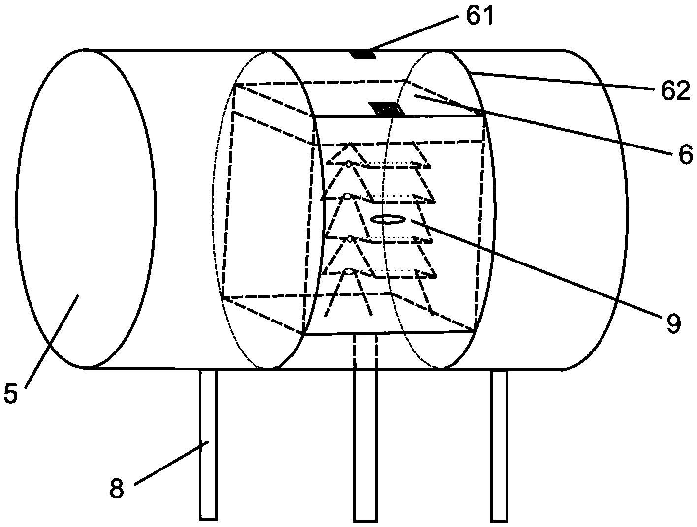
[0022] See figure 1 with figure 2 The dynamic thermal protection performance evaluation device according to a preferred embodiment of the present invention is used to fix the fabric to be tested to test the fabric (not labeled). The dynamic thermal protection performance evaluation device includes a support 8, a human body dynamic simulation device arranged on the support 8 to fix the fabric to be tested and promote deformation of the fabric to be tested, a disaster source 4 arranged on the side of the human body dynamic simulation device, and a disaster source 4 The heat flow sensor 6 arranged on both sides of the fabric to be tested, the air layer dynamic change device 3 connected with the heat flow sensor 6, and the data acquisition and program control system 7.
[0023] The human body dynamic simulation device includes a human body simulator 5 that is held against the fabric to be tested and a stretching device 2 that clamps both ends of the fabric to be tested. The human body simulator 5 is fixed on the bracket 8. The human body simulator 5 has a resisting wall (not numbered) that resists the fabric to be tested to deform the fabric to be tested, and the resisting wall and the disaster source 4 Set oppositely on both sides of the fabric to be tested. In an embodiment, the human body simulator 5 is used to simulate a human leg, and is cylindrical, and the holding wall is bent in an arc shape to cause the fabric to be tested to be bent and deformed. The human body simulator 5 has a diameter of 200 mm and a length of 150 mm, and is made of inorganic composite materials, so that its thermal diffusion performance is close to that of the skin, and it also has waterproof performance. The human body simulator 5 is provided with a hollow portion (not labeled), and the hollow portion and the fabric to be tested are arranged on both sides of the resisting wall opposite to each other. In an embodiment, the resisting wall is arranged upward, and the hollow portion is located at the resisting wall. At the rear of the holding wall, in other embodiments, the holding wall may also face other ways, such as being arranged downward. The hollow part is a square hole with a width of 100 mm.
[0024] The stretching devices 2 are two relatively fixed on the two ends of the fabric to be tested, and are located on both sides of the human body simulator 5 respectively. Each stretching device 2 includes a weight 25, a connecting belt 23, a sample holder 21, a spring gauge 24, a miniature lifting platform 26, a fixed pulley 22 and a fixing frame 27. The sample holder 21 has herringbone teeth (not labeled) for clamping the fabric to be tested and fixed with screws (not labeled). The fixing frame 27 fixes the fixed pulley 22. The fixed pulley 22 is located inside the connecting belt 23 and resists the connecting belt 23, so that the specimen holder 21 is placed at 45°, thereby combining with the curved and bent resisting wall to realize waiting Different bending, stretching and shear deformation states of the fabric are measured. One end of the sample holder 21 is connected to the fabric to be tested, and the other end is connected to the spring gauge 24 through a connecting strap 23. The weight 25 is connected to the spring meter 24, and the weight 25 is placed on the micro-lifting platform 26. The micro-lifting platform 26 is connected to the data acquisition and program control system 7 and is controlled by the data acquisition and program control system 7. The program in the program control system 7 adjusts the height of the micro-lifting platform 26, and changes the elongation of the spring gauge 24 to control the deformation degree of the fabric to be tested, thereby simulating the dynamic deformation of the fabric to be tested under the condition of human motion. In other embodiments, the connecting strap 23 can be directly connected to the weight 25, so that the amount of stretching can be changed by changing the weight of the weight 25. In addition, the micro-lifting platform 26 may not be provided; or, the stretching device 2 may Only one end of the fabric to be tested is clamped, or only the two ends of the fabric to be tested are clamped by a stretching device 2; in other embodiments, the stretching device 2 may not include a spring gauge 24 and a miniature lifting platform 26. Fixed pulley 22 and fixed frame 27.
[0025] The air layer dynamic changing device 3 and the heat flow sensor 6 are both arranged in the hollow part. The air layer dynamic changing device 3 is an air cylinder and includes a cylinder block 31 fixed in the hollow part and a plunger 32 mounted on the cylinder block 31, The plunger 32 can move along the cylinder 31, the cylinder 31 has an opening (not numbered) facing the resisting wall, the heat flow sensor 6 is arranged on the plunger 32, and the plunger 32 drives the heat flow sensor 6 to face The resisting wall moves, thereby changing the distance between the heat flow sensor 6 and the resisting wall, and simulating the change in the size of the air layer under the clothes caused by human movement. The air layer dynamic change device 3 is signally connected to the data acquisition and program control system 7 and is controlled by the data acquisition and program control system 7. By controlling the lifting speed and frequency of the plunger 32 of the air layer dynamic change device 3, change The distance between the heat flow sensor 6 and the fabric to be measured, thereby simulating the size change of the air layer under the clothes caused by human movement. In other embodiments, the air layer dynamic changing device 3 can also be other structures, such as an automatic elevator.
[0026] The heat flow sensor 6 is a skin sensor, and includes a base 62 provided on the plunger 32 and a thermocouple 61 provided on the base 62. The base 62 and the human body simulator 5 are made of the same inorganic composite material. The base 62 has a mounting surface (not numbered) facing the resisting wall. The mounting surface is an arc-shaped surface. The curvature of the mounting surface and the resisting The curvature of the wall is the same. Since the cylinder body 31 has an opening facing the resisting wall, and the curvature of the mounting surface is the same as the bending curvature of the resisting wall, the mounting surface can be made to abut against the resisting wall, and the thermocouple 61 can be attached to the resisting wall. The heat flow sensor 6 is connected to a data acquisition and program control system 7, and the data acquisition and program control system 7 is connected to a PCI-6251 multifunctional DAQ data board and self-made program control software. The thermocouple 61 is embedded on the mounting surface, and the thermocouple 61 is a T-type thermocouple, and the number is three.
[0027] The disaster source 4 may be one or more of a convection disaster heat source, a radiation disaster heat source, a high temperature liquid disaster heat source, and a high temperature steam disaster heat source, so that the dynamic thermal protection performance evaluation device of the present invention has good scalability. In this embodiment, the disaster source 4 is a high-temperature liquid disaster heat source. The high-temperature liquid disaster heat source includes a water tank 41, a spray head 46 facing the fabric to be tested, a conveying pipe 44 connecting the water tank 41 and the spray head 46, and a water pump 43 and a control valve 45 arranged on the conveying pipe 44. The water tank 41 is equipped with a temperature control device 42, which can automatically control the heater 42 to ensure a constant liquid temperature. The water pump 43 has a pressure control system that can set the pressure of the high-temperature liquid. A three-way ball valve (not shown) is installed on the transfer pipeline 44, which is connected to the water pump 43, the spray head 46 and the water tank 41 respectively. The control valve 45 is a solenoid valve switch. The solenoid valve switch 45 is connected to the data acquisition and program control system 7. When the solenoid valve switch 45 is closed, the liquid in the water tank 41 can circulate through the transmission pipeline 44 to ensure the transmission pipeline The temperature of the liquid in 44 is constant to avoid a drop in the temperature of the sprayed liquid at the beginning of the experiment and affect the accuracy of the experiment. The nozzle 46 is made of a stainless steel tube with a diameter of 6-8 mm.
[0028] During the experiment, fix the two ends of the fabric to be tested on the two sample holders 21 respectively, select the weight of the weight 25 according to the experimental requirements to calculate the maximum deformation degree of the fabric to be tested, and adjust the height of the two miniature lifting platforms 26 Change the dynamic deformation of the fabric to be tested; set the changing frequency and speed of the air layer dynamic changing device 3, adjust the dynamic change of the air layer size between the heat flow sensor 6 and the fabric to be tested, so as to realize the skin and the test under the dynamic conditions of the human body Simulation of dynamic changes between the fabrics; finally, the data acquisition and program control system 7 controls the ejection pressure and time of the high temperature liquid disaster, and the data acquisition and program control system 7 collects the data of the heat flow sensor 6, so as to perform the thermal protection performance of the tested fabric Evaluation. In the experiment, the stretching device 2 and the air layer dynamic change device 3 can be used in conjunction with each other to simulate the process of human joint movement; or used alone to simulate fabric deformation or air layer size changes.
[0029] To sum up, the dynamic deformation adjustment of the fabric to be tested is realized by the human body simulator 5 and the stretching device 2. The air layer dynamic changing device 3 is set and the air layer dynamic changing device 3 drives the heat flow sensor 6 relative to the human body simulator 5. The resistance wall moves to change the distance between the heat flow sensor 6 and the fabric to be tested, to simulate the change in the size of the air layer under the clothes caused by human movement, so as to more realistically simulate the protection of the fabric deformation caused by the movement of the human joints in the working environment The performance makes up for the impact of dynamic factors on the thermal protection performance ignored by the existing protection performance evaluation device, and has very important practical significance for protecting the life safety of professional personnel and developing high-tech thermal protection equipment. In addition, the human body dynamic simulation device is simple in design and low in cost; the air layer dynamic change device 3 and the miniature lifting platform 26 can be controlled through the data acquisition and program control system 7, so that the operation is safe and convenient.
[0030] The above are only the preferred embodiments of the present invention and are not intended to limit the present invention. It should be pointed out that for those of ordinary skill in the art, several improvements can be made without departing from the technical principles of the present invention. And modifications, these improvements and modifications should also be regarded as the protection scope of the present invention.