
Optically controlled phased array radar front end transmitting and receiving method and device

An optically controlled phased array, radar front-end technology, applied in radio wave measurement systems, instruments, etc., can solve problems such as complex structures, and achieve the effects of simplifying system structure, reducing costs, and improving utilization.

Inactive Publication Date: 2015-01-28
SHANGHAI SPACEFLIGHT ELECTRONICS & COMM EQUIP RES INST
View PDF6 Cites 29 Cited by
  • Summary
  • Abstract
  • Description
  • Claims
  • Application Information

AI Technical Summary

Problems solved by technology

[0005] The purpose of the present invention is to propose a method and device for transmitting and receiving the front end of an optically controlled phased array radar, so as to solve the problem that the transmitting and receiving work of the existing optically controlled phased array radar is completed by different parts of the equipment, and the structure is complicated

Method used


Image

  • Optically controlled phased array radar front end transmitting and receiving method and device
  • Optically controlled phased array radar front end transmitting and receiving method and device
  • Optically controlled phased array radar front end transmitting and receiving method and device

Examples


Embodiment Construction

[0040] A specific embodiment of the present invention is given below in conjunction with the accompanying drawings. This embodiment is implemented on the premise of the technical solution of the present invention, and detailed implementation methods and processes are given, but the protection scope of the present invention should not be limited to the following embodiments.

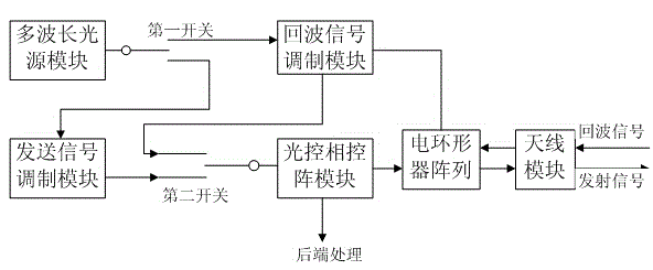
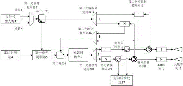
[0041] Such as figure 1 As shown, the transmitting and receiving device of the optically controlled phased array radar front end of the present invention includes: a multi-wavelength light source module, a transmission signal modulation module, an echo signal modulation module, an optically controlled phased array module and an antenna module, and also includes a first A switch, a second switch and an array of electric circulators. The fixed end of the first switch 3 is connected to the multi-wavelength light source module, the two optional ends of the first switch 3 are respectively connected to the tra...


PUM


Abstract

The invention provides an optically controlled phased array radar front end transmitting and receiving method and a device. The device is based on wavelength division multiplexing, radar radio frequency signals are loaded onto multi-wavelength optical signals when signals are transmitted, and the signals are inputted to an optical delay network; then, the signals are converted into phase-shift electric signals via an optical wavelength division demultiplexer and a photoelectric converter, and the electric signals are transmitted via a microwave antenna array; and when the signals are received, the received electric signals are loaded onto a multi-wavelength optical carrier, and the optical signals are converted into phase-compensation electric signals via a photoelectric conversion array for subsequent processing after passing through the wavelength division multiplexing optical delay network. An optical switch and an electrical switch are used to carry out time division multiplexing on a multi-wavelength laser source, the wavelength division multiplexing optical delay network, the photoelectric conversion array and other devices and structures in the case of transmitting and receiving of the optically controlled phased array radar, repeated use of key devices can be fully realized, the optically controlled phased array radar transmitting and receiving structure is simple and compact, and the cost of the optically controlled phased array radar is reduced.

Description

technical field [0001] The invention belongs to the technical field of optically controlled phased array radar, in particular to a method and device for transmitting and receiving the front end of optically controlled phased array radar. Background technique [0002] Optically controlled phased array radar makes full use of the advantages of large optical bandwidth, low optical fiber transmission loss, and immunity from electromagnetic interference to solve the problems of broadband and aperture transition compensation faced by microwave phased array radar. Since the concept of optically controlled phased array radar was proposed, many units at home and abroad have conducted research on optically controlled phased array radar. [0003] Optically controlled phased array radar based on wavelength division multiplexing technology, the number of optical carrier wavelengths corresponds to the number of phased array antenna sub-arrays, and can simultaneously control the delay of m...

Claims


Application Information

Patent Timeline
IPC IPC(8): G01S7/28G01S7/35
CPCG01S7/28
Inventor 李曙光徐显文薛峰
Owner SHANGHAI SPACEFLIGHT ELECTRONICS & COMM EQUIP RES INST
Learn More