Broadband grid antenna array

An antenna array and grid technology, which is applied in the field of wireless communication, can solve the problems of increasing the processing cost and complexity of the antenna, and achieve the effect of saving the production cost, simplifying the feeding network and satisfying the broadband communication system.

Inactive Publication Date: 2015-01-28
SOUTH CHINA UNIV OF TECH
View PDF7 Cites 18 Cited by
  • Summary
  • Abstract
  • Description
  • Claims
  • Application Information

AI Technical Summary

Problems solved by technology

[0005] 2) In 2011, YueHui Cui et al. published an article titled "Novel Dual-Broadband Planar Antenna and Its Array for 2G / 3G / LTE Base Stations" on IEEE TRANSACTIONS ON ANTENNAS AND PROPAGATION, and proposed an antenna for base stations Array, the antenna has two radiation bands of low frequency and high frequency, which can meet the frequency band requirements of 2G / 3G / LTE, but this antenna array requires a complex feeding network, which increases the processing cost of the antenna

Method used


Image

  • Broadband grid antenna array
  • Broadband grid antenna array
  • Broadband grid antenna array

Examples


Embodiment 1

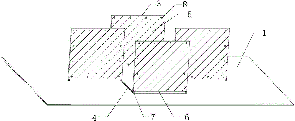
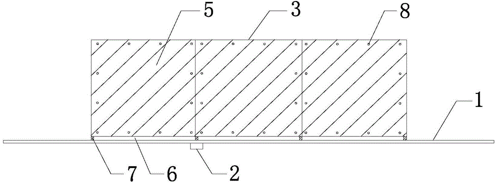
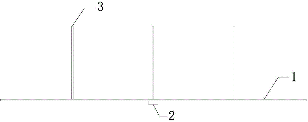
[0031] Such as Figure 1 to Figure 4 As shown, the broadband grid antenna array of the present embodiment includes a reflective floor 1, a coaxial line 2 and four radiation units 3 erected on the reflective floor 1, and the reflective floor 1 and the four radiation units 3 all adopt PCB boards ( The dielectric constant of the medium is 2.55), and the shapes are all rectangular; the upper layer of the reflective floor 1 is provided with four microstrip transmission lines 4 connecting each radiation unit 3, and the lower floor is a metal floor; two of the four radiation units 3 The radiating units 3 are arranged vertically, and two radiating units 3 are arranged horizontally (that is to say, the radiating units 3 arranged vertically have one column, and the radiating units 3 arranged horizontally have one row), and together form a grid antenna array on the reflective floor 1; The length of each microstrip transmission line 4 is one-half of the wavelength corresponding to the cen...

Embodiment 2

[0036] Such as Figure 7 As shown, on the basis of the structure of Embodiment 1, the horizontal expansion is carried out to form a grid antenna array of ten radiation units 3 on the reflective floor 1. It can be seen that the radiation units 3 arranged in the vertical direction have three columns, and the radiation units arranged in the horizontal direction 3 has three rows.

Embodiment 3

[0038] Such as Figure 8 As shown, on the basis of the structure of Embodiment 1, horizontal and vertical expansion are carried out simultaneously, and a grid antenna array of sixteen radiating units 3 is formed on the reflective floor 1. It can be seen that there are five columns of radiating units 3 arranged vertically. There are five rows of radiation units 3 arranged laterally.

[0039] In the above-mentioned embodiment, the PCB board adopted by the reflector and each radiation unit can be made of any dielectric material of FR4, polyimide, polytetrafluoroethylene glass cloth and co-fired ceramics; the metal floor, radiation The metal used for the patches and metal sheets is any one of aluminum, iron, tin, copper, silver, gold and platinum, or any alloy of aluminum, iron, tin, copper, silver, gold and platinum.


PUM


Abstract

The invention discloses a broadband grid antenna array. The broadband grid antenna array comprises a reflection floor and a plurality of radiating elements uprightly arranged on the reflection floor, wherein a plurality of micro strip transmission lines respectively connected with all the radiating elements are arranged on the upper layer of the reflection floor, the plurality of the radiating elements on the reflection floor form a grid antenna array in surrounding mode, radiation patches cover the obverse side and the reverse side of each radiating element, a section of each radiation patch, located on the lower portion of each of the obverse side and the reverse side of each radiating element, is corroded so as to expose a medium portion, metal slices are respectively pasted at the left end and the right end of each exposed medium portion, the metal slices are respectively connected with the radiation patches and the micro strip transmission lines, a plurality of via holes are formed in the periphery of each radiating element, and the plurality of the via holes penetrate through the radiation patches on the obverse sides and the reverse sides of each radiating element. The broadband grid antenna array is provided with a simple feed network, has the advantages of being large in bandwidth, easy to process, low in cost and the like, and can meet requirements of a broadband communication system.

Description

technical field [0001] The invention relates to an antenna array, in particular to a broadband grid antenna array, which belongs to the field of wireless communication. Background technique [0002] Antenna is a device used to transmit and receive electromagnetic waves in wireless devices. Anything that uses electromagnetic waves to transmit information relies on antennas to work. With the continuous development of communication technology, the amount of information transmitted in wireless communication is increasing, and the requirements for antennas are also getting higher and higher. Antennas are developing in the direction of broadband, intelligence, low profile, and low cost. Most of the currently used antenna arrays need to add a feed network to ensure the performance of the antenna, but this will not only increase the return loss of the antenna but also increase the cost of the antenna, making the structure of the antenna complicated; while the grid antenna It is a ...

Claims


Application Information

Patent Timeline
Patent Type & Authority Applications(China)
IPC IPC(8): H01Q21/00H01Q1/36H01Q1/48
Inventor 王世伟孙光华黄启凯褚庆昕
Owner SOUTH CHINA UNIV OF TECH
Why Eureka
Try Eureka