Rotor iron core convenient to produce

A rotor core and iron core technology, applied in the field of machinery, can solve problems such as lack of market competitiveness and low production efficiency, and achieve the effects of reducing manufacturing costs, simplifying workload, and low noise

Inactive Publication Date: 2015-02-04
HANGZHOU MOEN MOTOR
View PDF7 Cites 2 Cited by
  • Summary
  • Abstract
  • Description
  • Claims
  • Application Information

AI Technical Summary

Problems solved by technology

Although it has a simple, compact, reasonable structure, and obvious effects; without changing the structural material and ensuring that the mechanical properties of the motor are qualified, a short-circuit ring is used on the rotor core; when the motor starts, the rotor There are a series of advantages such as the opposite direction of the two sections of the iron core; however, due to the limitation of its structure, in the manufacturing process, three iron core groups made by multiple molds are still required to form a rotor core group by superimposing each other. As a result, its production efficiency is low and it does not have market competitiveness

Method used


Image

  • Rotor iron core convenient to produce

Examples


Embodiment 1

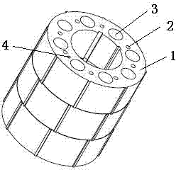
[0014] Such as figure 1 As shown, a rotor core that is easy to manufacture includes several iron sheets 1 stacked together. The iron sheets 1 are provided with several rivet holes 2 and cooling holes 3 that are easy to pass through. The iron sheets 1 Evenly distributed and stacked into three iron core groups connected together, which are the first iron core group, the second iron core group and the third iron core group; the rotor structure composed of three iron core groups can make the motor run more smoothly , the torque ripple is smaller. Each iron core group is composed of several iron chips 1, and each iron chip 1 is provided with two groups of evenly distributed rivet holes 2, each group of rivet holes is four, and each iron chip 1 has There are two keyways, and the two keyways are distributed at 45° in the circumferential direction. One rivet hole 2 in one set of rivet holes is on the same radius line as one of the keyways, and one rivet hole 2 in the other set of riv...

Embodiment 2

[0016] Such as figure 1 As shown, a rotor core that is easy to manufacture includes several iron sheets 1 stacked together. The iron sheets 1 are provided with several rivet holes 2 and cooling holes 3 that are easy to pass through. The iron sheets 1 Evenly distributed and laminated into three iron core groups connected together, which are the first iron core group, the second iron core group and the third iron core group; each iron core group is composed of several iron chips 1, so Each iron chip 1 described above is provided with two groups of evenly distributed rivet holes 2, and each group of rivet holes 2 is 4. At the same time, each iron chip 1 is provided with two key grooves, and the two key grooves are arranged in the circumferential direction. 55°distribution, one rivet hole 2 in one group of rivet holes is on the same radius line as one of the keyways, and one rivet hole 2 in the other group of rivet holes is on the same radius line as the other keyway. 1 is provid...


PUM


Abstract

The invention discloses a rotor iron core convenient to produce. The rotor iron core comprises a plurality of iron core sheets which are superposed together. Each iron core sheet is provided with a plurality of rivet holes convenient to run through and heat dissipation holes; the iron core sheets are uniformly distributed and superposed to form three iron core groups which are connected together. Each iron core group is formed by the plurality of same iron core sheets; each iron core sheet is provided with two groups of uniformly-distributed rivet holes; meanwhile, each iron core sheet is provided with two key grooves; and the iron core sheet is provided with a balance hole in the circumference of the heat dissipation hole. The rotor iron core has the advantages of reducing production labor hour, simplifying manufacture steps, reducing production cost wholly, being convenient for rivets to pass through, being stable in motor operation, being small in torque pulsation and motor noise, simplifying dynamic balance correction work load, and reducing manufacture cost of the motor.

Description

technical field [0001] The invention relates to the technical field of machinery, and relates to a rotor, in particular to a rotor core which is easy to manufacture. Background technique [0002] The rotor core (magnetic core) plays a pivotal role in the entire motor. It is used to increase the magnetic flux of the inductance coil and realize the maximum conversion of electromagnetic power. It has a wide range of applications, such as stepper motors, AC and DC motors, geared motors, external rotor motors, shaded pole motors, and synchronous asynchronous motors. For the finished motor, the role of the motor core in the motor accessories is more critical. To improve the overall performance of a motor, it is necessary to improve the performance of the motor core. Usually this kind of performance can be solved by improving the material of the iron core punching sheet, adjusting the magnetic permeability of the material, and controlling the size of the iron loss. A good motor ...

Claims


Application Information

Patent Timeline
Patent Type & Authority Applications(China)
IPC IPC(8): H02K1/22H02K1/32
CPCH02K1/22H02K1/32
Inventor 周建华严其斌
Owner HANGZHOU MOEN MOTOR
Why Eureka
Try Eureka