Low Electrical Stress zcs‑pwm Superbuck Converter

An electrical stress and converter technology, applied in high-efficiency power electronic conversion, regulation of electrical variables, conversion of DC power input to DC power output, etc. The effect of continuous current and small grid pollution

Inactive Publication Date: 2017-03-29
NANTONG UNIVERSITY +1
View PDF2 Cites 0 Cited by
  • Summary
  • Abstract
  • Description
  • Claims
  • Application Information

AI Technical Summary

Problems solved by technology

In order to realize the miniaturization and light weight of the Superbuck converter, it is necessary to increase the switching frequency, however, the current tail of the IGBTs when they are turned off will cause a large turn-off loss

Method used


Image

  • Low Electrical Stress zcs‑pwm Superbuck Converter
  • Low Electrical Stress zcs‑pwm Superbuck Converter
  • Low Electrical Stress zcs‑pwm Superbuck Converter

Examples


Embodiment example

[0104] According to the above analysis, a ZCS-PWM Superbuck converter is designed, whose input voltage U in =510V, output voltage U o =300V, output power P o =1.5kW, switching frequency f s = 80kHz. The parameters are designed as follows:

[0105] Filter inductance L 1 calculation

[0106] According to the basic parameters of the converter, the average value of the input current is:

[0107]

[0108] The duty cycle is:

[0109]

[0110] Calculated on the basis that the current ripple does not exceed 20%.

[0111]

[0112]

[0113] take L 1 =2.6mH

[0114] Filter inductance L 2 calculation

[0115]

[0116]

[0117] take L 2 =4mH

[0118] Energy storage capacitor C 1 calculation

[0119] From the balance of the volt-second product: U C1 =U in

[0120]

[0121] can be obtained from the above formula

[0122]

[0123] Calculated on the basis that the voltage ripple does not exceed 1%, C 1 ≈0.15uF, take C 1 =0.47uF

[0124] Output filt...


PUM


Abstract

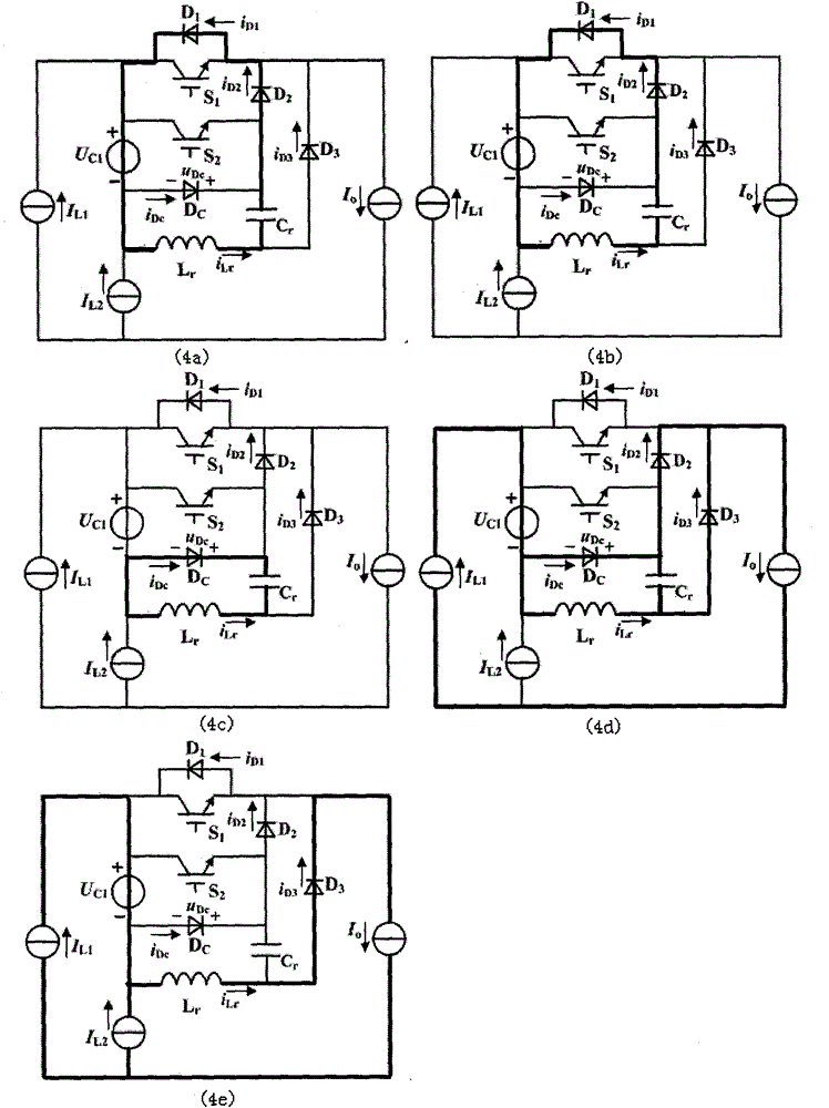
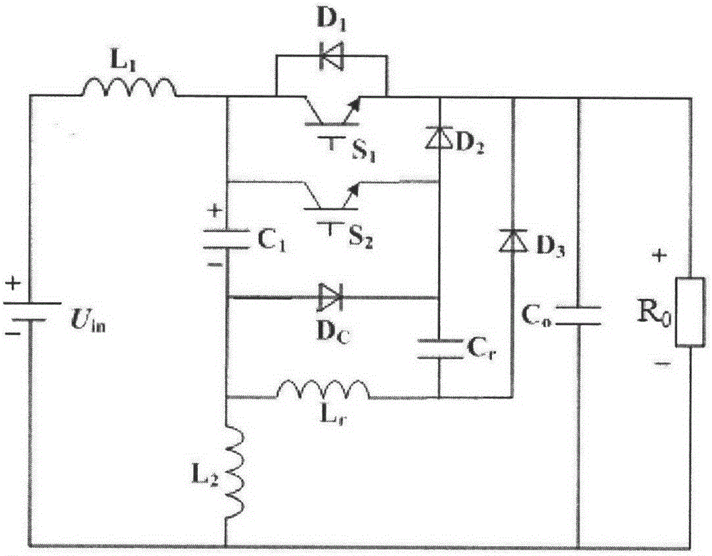
The invention discloses a ZCS-PWM Superbuck converter with low electrical stress, comprising a main switch circuit and an auxiliary circuit, the main switch circuit includes a main switch tube and a diode anti-parallel with the main switch tube, the auxiliary circuit includes an auxiliary switch tube, and the auxiliary switch An auxiliary diode is connected between the emitter of the tube and the emitter of the main switching tube, and a resonant branch is connected to the emitter of the auxiliary switching tube. A clamping diode is connected, an energy storage capacitor is connected between the anode of the clamping diode and the collector of the auxiliary switching tube, and a freewheeling current is connected between the emitter of the main switching tube and the connection node of the resonant capacitor and the resonant inductance in the resonant branch. diode. The converter combines the soft switching technology and the Suerbuck converter, so that it has the advantages of low electrical stress, small volume and weight, high efficiency, long life, and little pollution to the power grid.

Description

technical field [0001] The invention relates to a switch circuit of a ZCS-PWM converter, in particular to a ZCS-PWM Superbuck converter with low electrical stress, which is especially suitable for electric vehicle charging. Background technique [0002] With the depletion of oil resources, the development of electric vehicles has been favored by people in recent years, and the governments of various countries have also introduced corresponding policies to encourage the development of electric vehicles. The use of electric vehicles will become a trend in future development. In this case, the charging device plays a key role. In order to reduce line loss, high-power DC charging devices are generally powered by a three-phase power supply, and its rectified voltage is about 500V, which is higher than the power battery terminal voltage (300V). Therefore, the charging device generally adopts a buck converter as the main circuit topology. Existing information shows that the Buck ...

Claims


Application Information

Patent Timeline
Patent Type & Authority Patents(China)
IPC IPC(8): H02M3/155
CPCH02M3/156H02M3/1566Y02B70/10
Inventor 秦岭孔笑笑张佳祺胡茂王亚芳王胜锋
Owner NANTONG UNIVERSITY
Why Eureka
Try Eureka