Solar member for building

A technology for solar energy and construction, applied in sustainable buildings, electrical components, renewable energy integration, etc., can solve problems such as affecting the reliability and life of material bonding, high thermal resistance of photovoltaic module backplanes, and inability to effectively absorb thermal energy. , to achieve the effect of good safety protection performance, stable and reliable insulation performance, and easy maintenance

Active Publication Date: 2015-02-04
ANHUI CHANGYUAN GREEN ENERGY
View PDF9 Cites 3 Cited by
  • Summary
  • Abstract
  • Description
  • Claims
  • Application Information

AI Technical Summary

Problems solved by technology

Although this patent can realize the function of photovoltaic power generation and solar heat collection, the solar heat collector tube is in contact with the solar cell through the back plate of the photovoltaic module. Due to the high thermal resistance of the back plate of the photovoltaic module, it cannot effectively absorb a large amount of heat energy generated by the solar cell during operation, which affects the photovoltaic power generation. The power generation efficiency of components and the heat energy absorption of solar collector tubes; the inlets and outlets of solar collector tubes are located on both sides of the module modules, and the inlets and outlets of adjacent module modules are directly connected. A large number of collector tube connections in the system lead to complicated connections, difficult sealing and heavy maintenance workload ;The solar collector tube and the photovoltaic module are bonded by hot-melt adhesive film, and the high temperature generated during work directly affects the bonding reliability and life of the material

Method used


Image

  • Solar member for building
  • Solar member for building
  • Solar member for building

Examples


Embodiment 1

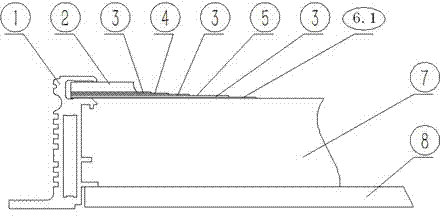
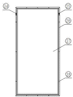
[0055] see figure 1 , 3 and Figure 8-11 , the present invention includes a photovoltaic module, a negative connector 24, a positive connector 25, a junction box 11 and a frame 1, and the photovoltaic module is composed of a glass panel 2, a solar cell 4, an adhesive 3, an insulating film 5, and a metal plate 6.1 (metal The plate is used as the back plate of the photovoltaic module); the contact surface of the metal plate 6.1 and the solar cell 4 is treated with an insulating layer or the insulating film 5 is bonded; the glass panel 2, the solar cell 4, the insulating film 5 and the metal plate 6.1 are formed by bonding the adhesive 3 It is a whole and encapsulated in the frame 1; the metal plate 6.1 is in close contact with the frame 1. The heating device in the junction box 11, or the heating device 12 is installed on the printed circuit board 52, and is fixed on the frame 1 (or on the metal plate 6.1); the positive L-shaped connector 25 and the negative L-shaped connecti...

Embodiment 2

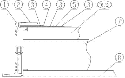
[0059] see figure 2 , 3 and Figure 8-11 , the present invention includes a photovoltaic module, a negative connector 24, a positive connector 25, a junction box 11 and a frame 1, and the photovoltaic module is composed of a glass panel 2, a solar cell 4, an adhesive 3, an insulating film 5, and a solar collector 6.2 (The solar collector is used as the backboard of the photovoltaic module); the contact surface of the solar collector 6.2 and the solar cell 4 is treated with an insulating layer or bonded with an insulating film 5; the glass panel 2, the solar cell 4, the insulating film 5 and the solar heat collector The device 6.2 is formed as a whole by bonding with the adhesive 3 and encapsulated in the frame 1; the solar heat collector 6.2 is in close contact with the frame 1. The heating device in the junction box 11, or the heating device 12 is installed on the printed circuit board 52, and is fixed on the frame 1 (or on the solar collector 6.2); the positive L-shaped c...

Embodiment 3

[0066] see Figure 12 , 13 In the present invention, the structural design of the frame of the traditional photovoltaic module is changed to meet the structural requirements of the building envelope and the functional requirements of the photovoltaic module. On the inner side of the frame, the photovoltaic module installation groove and the positioning boss of the component back plate are designed. Two vertical bosses are designed on the inner side of the frame, namely the junction box limiting boss 15 and the junction box anti-slip boss 16, which cooperate with the corresponding grooves of the junction box shell to fix the junction box. A plurality of grooves are designed on the outside of the frame, that is, the frame structure groove 21, to increase the structural strength and increase the contact surface between the sealant and the frame surface when filling the sealant. The arc-shaped groove on the outside of the frame, the sealing strip installation groove 20 correspon...


PUM


Abstract

The invention relates to a solar member for a building. The solar member comprises a photovoltaic assembly, a junction box, a connector, a frame, a filling material and a member backboard. A solar heat collector or a metal plate is employed as a photovoltaic assembly backboard, and a heating electronic device and the frame or the photovoltaic assembly backboard are contacted for heat dissipation; the photovoltaic assembly and the member backboard are installed in a fixation groove corresponding to the frame to form an enclosed space, and an integral member module is formed by bonding the filling material; the outer side surface of the frame is provided with a radiator and a heat conduction pipe for conducting solar energy to a solar heat collection system; and a refrigeration and heating apparatus is integrated on the photovoltaic assembly backboard and the member backboard, and an isolation layer is clamped between the photovoltaic assembly backboard and the member backboard. According to the invention, the solar member for the building can be used for photovoltaic generating and solar heat collection and temperature adjustment, can directly replace a decoration material, an insulation material, a waterproof material, an exterior-protected construction material and an air conditioning device on the roof or the wall of the building, and can also be integrally installed with the roof or the wall of an existing building so as to realize photovoltaic building integration.

Description

technical field [0001] The invention relates to an industrial component product with the functions of photovoltaic power generation, solar heat collection and building exterior protection, which can be used for photovoltaic power generation, solar heat collection and temperature regulation, and can directly replace the decorative materials and heat preservation of building roofs or walls. Materials, waterproof materials, enclosure structure materials and air-conditioning equipment; it can also be installed and fixed with the roof or wall of the existing building in an integrated way to realize building-integrated photovoltaics and building-integrated solar energy. [0002] Background technique [0003] Due to energy demand and the need of sustainable human development, photovoltaic power generation and solar heat collection, especially solar building integration, are one of the important technical means. The photovoltaic modules and solar heat collectors in the prior art ar...

Claims


Application Information

Patent Timeline
Patent Type & Authority Applications(China)
IPC IPC(8): H02S30/10H02S40/42H02S40/34
CPCH02S20/00H02S30/00H02S40/00Y02B10/10Y02E10/50
Inventor 余晓东
Owner ANHUI CHANGYUAN GREEN ENERGY
Why Eureka
Try Eureka