A hydraulically driven spray device

A technology of injection device and hydraulic drive, which is used in muffler devices, exhaust devices, engine components, etc., can solve the problems of high machining accuracy, high cost, complex structure, etc., achieve high accuracy, facilitate deburring, and ensure response. effect of speed

Active Publication Date: 2017-07-14
KAILONG HIGH TECH
View PDF9 Cites 0 Cited by
  • Summary
  • Abstract
  • Description
  • Claims
  • Application Information

AI Technical Summary

Problems solved by technology

[0003] The SCR injection system is an important part of the SCR post-treatment system, and its injection device is a key component of the entire SCR injection system. At present, the existing injection devices for the SCR injection system generally have complex structures, high machining accuracy and high cost. Shortcomings

Method used


Image

  • A hydraulically driven spray device
  • A hydraulically driven spray device
  • A hydraulically driven spray device

Examples


Embodiment Construction

[0019] The technical solutions of the present invention will be further described below in conjunction with the accompanying drawings and through specific implementation methods.

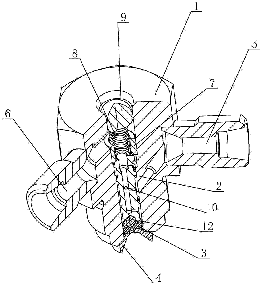
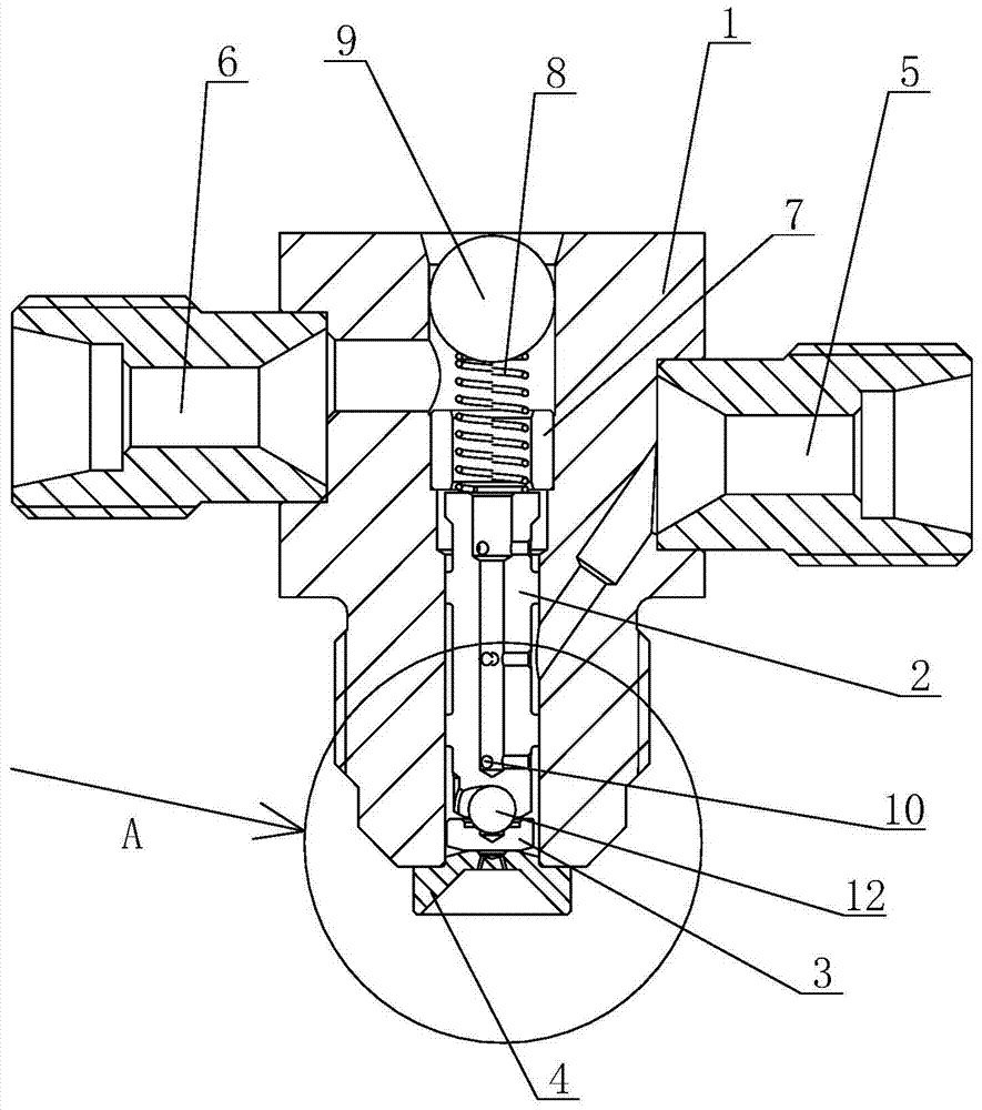
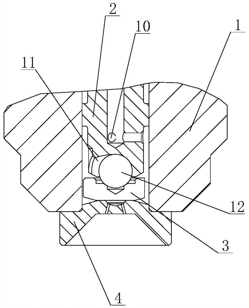
[0020] see Figure 1 to Figure 3 As shown, in this embodiment, a hydraulically driven injection device includes a valve body 1, a valve stem 2, a valve core 3, a valve seat 4, a liquid inlet 5, a liquid outlet 6, a limit sleeve 7, and a spring 8 And adjusting steel ball 9, the valve seat 4 is set on the bottom of the valve body 1 and has a spray hole on it, the valve body 1 is provided with a liquid inlet 5 and a liquid outlet 6, and the valve The body 1 is provided with an accommodating cavity for the lead, and the accommodating cavity is provided with an adjusting steel ball 9, a spring 8, a limit sleeve 7, a valve stem 2 and a valve core 3 sequentially from top to bottom. The position sleeve 7 is used to constrain the stroke of the valve stem 2 and is set on the top of the valve stem 2, the bott...


PUM


Abstract

The invention discloses a hydraulically driven injection device, which comprises a valve body, a valve rod, a valve core, a valve seat, a liquid inlet, a liquid outlet and an elastic assembly, wherein the valve seat is arranged on the valve body The bottom of the valve body is provided with a spray hole, the valve body is provided with a liquid inlet and a liquid outlet, and the valve body is provided with an accommodating cavity for the lead, and the accommodating cavity is from top to bottom. An elastic assembly, a valve stem and a valve core are arranged in sequence, the elastic assembly presses on the top of the valve stem, a pressure relief hole is opened on the valve stem, a valve core is installed at the bottom of the valve stem, and the valve The bottom of the core is a plane structure, and the valve core is seated and pressed on the valve seat through a plane seal. The flow section of the liquid inlet port is larger than the flow section of the pressure relief hole on the valve stem. The above-mentioned hydraulically driven injection device utilizes fluid pressure difference to open and close the valve. It has the advantages of simple structure, easy processing, and low cost, and at the same time ensures the sealing and use requirements.

Description

technical field [0001] The invention relates to an injection device, in particular to a hydraulically driven injection device for an SCR injection system. Background technique [0002] SCR (Selective Catalyst Reduction) for diesel engine selective catalytic conversion system is installed in the exhaust system of diesel vehicles to catalytically reduce NOx in diesel engine exhaust to N 2 and O 2 The catalytic reduction device uses urea aqueous solution as the reducing agent. Urea aqueous solution is injected into the exhaust pipe upstream of the catalyst, and is hydrolyzed into CO under the action of exhaust gas temperature and airflow 2 And ammonia, ammonia as a reducing agent to reduce NOx into pollution-free nitrogen and water. The urea solution is injected quantitatively according to the engine operating conditions. [0003] The SCR injection system is an important part of the SCR post-treatment system, and its injection device is a key component of the entire SCR inj...

Claims


Application Information

Patent Timeline
Patent Type & Authority Patents(China)
IPC IPC(8): F01N3/28
Inventor 臧志成
Owner KAILONG HIGH TECH
Why Eureka
Try Eureka