Check patentability & draft patents in minutes with Patsnap Eureka AI!

Automatic calibration device and automatic calibration method of laser module collimating lens

A technology of collimating lens and laser module, applied in the directions of installation, optics, optical components, etc., can solve the problems of hidden safety hazards, long working hours, unavoidable human errors, etc., to improve the yield and efficiency, shorten the manufacturing cycle, and avoid artificial Effects of Calibration Errors

Active Publication Date: 2015-02-11
徐州奕创光电科技有限公司
View PDF5 Cites 12 Cited by
  • Summary
  • Abstract
  • Description
  • Claims
  • Application Information

AI Technical Summary

Problems solved by technology

There are inevitable human errors in human eye calibration, and it takes a long time to work. Because the laser needs to be lit, there are potential safety hazards

Method used


Image

  • Automatic calibration device and automatic calibration method of laser module collimating lens
  • Automatic calibration device and automatic calibration method of laser module collimating lens
  • Automatic calibration device and automatic calibration method of laser module collimating lens

Examples


Embodiment Construction

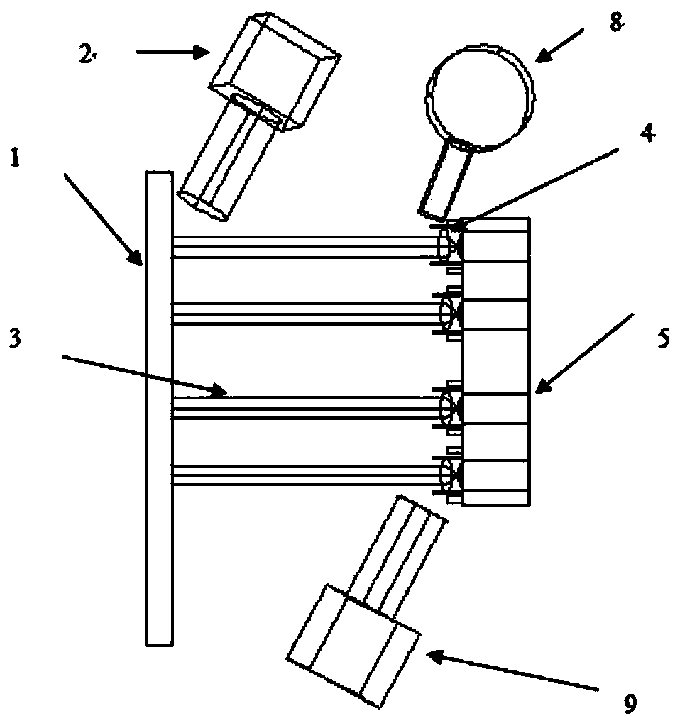
[0020] like figure 1 As shown, an automatic calibration device for a laser module collimator lens, including a spot calibration plate 1, a first CCD image alignment system 2, a collimator lens 4, a laser module 5, a robot arm 8, and a second CCD image alignment system 9 and dispensing system (not shown in the figure). The light spot calibration plate 1 is an aluminum plate, on which the light spot calibration position is marked as the calibration mark point 7 . The laser module 5 is used to emit the laser beam 3 , and the front end of the laser module 5 is opposite to the side of the spot calibration plate 1 provided with the calibration mark point 7 . The laser module 5 includes a laser and a deck for fixing the laser, and the deck is distributed in an equidistant matrix. The laser is evenly distributed after being fixed on the deck, which helps the laser to emit light evenly and has a better heat dissipation effect. The robot arm 8 is used to move and position the collima...


PUM


Abstract

The invention discloses an automatic calibration device and an automatic calibration method of a laser module collimating lens. The automatic calibration device comprises a spot calibration plate, a laser module for emitting laser beams, a collimating lens, an adhesive dispensing system, a first CCD (Charge Coupled Device) image alignment system, a machine arm and a second CCD image alignment system, wherein the spot calibration plate is provided with calibration mark points; the first CCD image alignment system is used for reading the positions of spots formed on the spot calibration plate by the laser beams and calculating the offset of the spots relative to the calibration mark points; the machine arm is used for moving and positioning the collimating lens according to the offset; the second CCD image alignment system is used for reading location parameters after the positioning of the collimating lens and transmitting the location parameters to the adhesive dispensing system to complete adhesive dispensing. The production automation of laser light source modules is realized, the manufacturing cycle is shortened, the manual calibration error is avoided, the rate of finished products and efficiency are improved, and meanwhile the potential safety hazards are further eliminated.

Description

technical field [0001] The invention relates to the production field of a laser module, in particular to an automatic calibration device and method for a collimating lens of a laser module. Background technique [0002] At present, the assembly of the collimating lens of the laser light source module is manual work. First, the laser is turned on, the collimating lens is manually calibrated, and then glue is manually dispensed and fixed. There are inevitable human errors in the human eye calibration, and it takes a long time to work. Because the laser needs to be lit, there are potential safety hazards. Contents of the invention [0003] Purpose of the invention: The present invention aims to provide an automatic calibration device and method for the collimating lens of a laser module that replaces manual calibration, avoids human errors, and eliminates potential safety hazards. [0004] Technical solution: An automatic calibration device for the collimating lens of a lase...

Claims


Application Information

Patent Timeline
IPC IPC(8): G02B27/30G02B7/02
CPCG02B27/30
Inventor 苏春阳李建春
Owner 徐州奕创光电科技有限公司
Features
  • R&D
  • Intellectual Property
  • Life Sciences
  • Materials
  • Tech Scout
  • Unparalleled Data Quality
  • Higher Quality Content
  • 60% Fewer Hallucinations
Learn More