Coaxial microwave plasma film-deposition equipment

A microwave plasma, microwave plasma technology, applied in the field of ions, to achieve the effect of effective process control and broad application prospects

Inactive Publication Date: 2015-02-18
CHANGZHOU INST OF DALIAN UNIV OF TECH
View PDF3 Cites 18 Cited by
  • Summary
  • Abstract
  • Description
  • Claims
  • Application Information

AI Technical Summary

Problems solved by technology

But this only applies to

Method used


Image

  • Coaxial microwave plasma film-deposition equipment
  • Coaxial microwave plasma film-deposition equipment
  • Coaxial microwave plasma film-deposition equipment

Examples


Embodiment 1

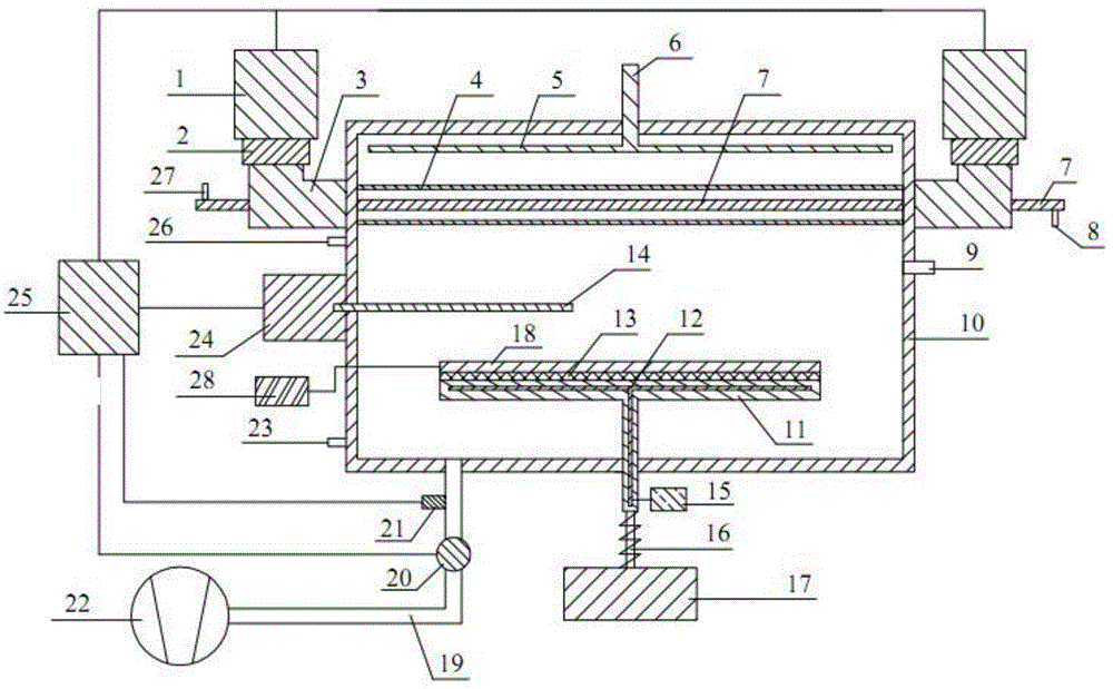
[0031] Such as figure 1 The device for coaxial microwave plasma deposition of thin films shown includes a vacuum chamber on which a coaxial microwave plasma source is fixedly installed, and the coaxial microwave plasma source includes a microwave generator, a waveguide, a coaxial cable Converter, quartz tube and inner electrode, wherein, the quartz tube is located inside the vacuum chamber and is fixedly installed on the two side walls of the vacuum chamber, and the coaxial converter is coaxially and symmetrically fixedly installed on both sides of the quartz tube through the outer side wall of the vacuum chamber. At the same time, the coaxial transformer is connected to the microwave generator through the waveguide, the inner electrode passes through the quartz tube and is fixed on the coaxial transformer, the inner electrode, the coaxial transformer, and the quartz tube are coaxial, and the vacuum chamber There is an inlet pipe on the top of the chamber, and the discharge ga...

Embodiment 2

[0044] Identical with embodiment 1 content, different technical parameters are:

[0045] (1) The bottom and top of the vacuum chamber are movably installed with a support platform, the lower end of the support platform protrudes from the vacuum chamber wall to connect with the position adjustment device, the position adjustment device is connected with the position control device, and the sample platform is detachably installed on the support platform, An insulating layer is arranged between the supporting platform and the sample platform;

[0046] (2) The microwave trigger mode of the microwave generator is external trigger, the microwave output mode is continuous mode, and the maximum output power of the continuous mode is 1500W.

[0047] (3) The coaxial microwave plasma sources fixedly installed on the vacuum chamber are arranged in parallel and equally spaced in 4 groups.

[0048] (4) 3 air guide tubes are installed at the lower end of the intake pipe, the air guide tubes...

Embodiment 3

[0053] Identical with embodiment 1 content, different technical parameters are:

[0054] (1) The bottom and side of the vacuum chamber are movably installed with a support platform, the lower end of the support platform protrudes from the vacuum chamber wall to connect with the position adjustment device, the position adjustment device is connected with the position control device, and the sample platform is detachably installed on the support platform , an insulating layer is set between the support platform and the sample platform;

[0055] (2) The microwave trigger mode of the microwave generator is external trigger, the microwave output mode is continuous mode, and the maximum output power of the continuous mode is 2000W.

[0056] (3) The coaxial microwave plasma sources fixedly installed on the vacuum chamber are arranged in 8 groups horizontally parallel and equally spaced.

[0057] (4) Seven air guide tubes are installed at the lower end of the intake pipe, each air gu...


PUM


Abstract

The invention discloses coaxial microwave plasma film-deposition equipment, and belongs to the field of plasma technology. The equipment comprises a vacuum chamber, wherein a coaxial microwave plasma source is fixedly mounted on the vacuum chamber; the coaxial microwave plasma source comprises microwave generators, waveguides, coaxial line convertors, a quartz tube and an inner electrode; the quartz tube is located in the vacuum chamber and fixedly mounted on two side walls of the vacuum chamber; the coaxial line convertors are coaxially, symmetrically and fixedly mounted at the two ends of the quartz tube via the outer side wall of the vacuum chamber; the coaxial line convertors are connected with the microwave generators via the waveguides; the inner electrode penetrates through the quartz tube and is fixed on the coaxial line convertors; the inner electrode, the coaxial line convertors and the quartz tube are coaxial; the equipment is further provided with an instrument for testing the electron density and the electron temperature of plasmas and automatic power and air pressure control equipment and system, can obtain stable high-controllability plasmas, and can realize efficient, stable and uniform film deposition; the equipment has high production efficiency and is low in production cost.

Description

technical field [0001] The invention belongs to the field of plasma technology, in particular to a device for depositing thin films by microwave plasma. Background technique [0002] With the application of microwave plasma in the preparation of semiconductor thin film materials, and semiconductor thin film materials, especially liquid crystal display materials and solar cells, tend to have large areas (> 30cm 2 ) development, the production of large area (> 30cm 2 ) Semiconductor thin film materials are the development direction of the future semiconductor industry, especially liquid crystal display materials and solar cells. [0003] However, the traditional capacitively coupled plasma (CCP) is far from meeting the requirements. There are several different methods for microwave-induced plasma discharge: [0004] (1) The microwave energy is coupled with the plasma generator. For example, a horn antenna with a window is used to separate the device into high and low ...

Claims


Application Information

Patent Timeline
IPC IPC(8): C23C16/517
CPCC23C16/517
Inventor 吴爱民林国强陆文琪邹瑞洵
Owner CHANGZHOU INST OF DALIAN UNIV OF TECH
Why Eureka
Try Eureka