Energy storage device

An energy storage device and energy storage technology, applied in the field of energy storage devices, can solve the problems of complex structure and price comparison of phase change energy storage equipment, unsuitability for large energy storage equipment, volume limitations, etc., to avoid poor water circulation, simple structure, The effect of increasing the guarantee rate

Active Publication Date: 2015-02-18
ENERGY RESOURCES INST HEBEI ACADEMY OF SCI
View PDF7 Cites 7 Cited by
  • Summary
  • Abstract
  • Description
  • Claims
  • Application Information

AI Technical Summary

Problems solved by technology

[0005] The structure of existing phase change energy storage equipment is complex, expensive to counterfeit, and inconvenient to use
And because of its complex structure, its overall volume is limited, so it is not suitable for large energy storage equipment

Method used


Image

  • Energy storage device
  • Energy storage device
  • Energy storage device

Examples


Embodiment 1

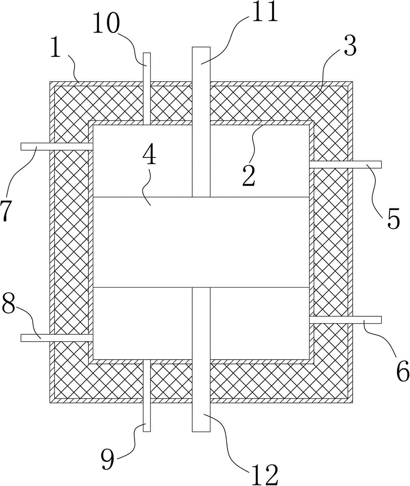
[0030] As attached figure 1 The energy storage device shown includes a cylindrical water tank and a cylindrical energy storage body 4 arranged inside the water tank.

[0031] The water tank includes an outer wall 1, an inner wall 2 of the water tank, and a thermal insulation interlayer 3 arranged between the outer wall 1 of the water tank and the inner wall 2 of the water tank; the side wall of the water tank is provided with a solar water inlet 8 and a solar energy for connecting with a solar heat collector. The backwater 7, and the heating water outlet 5 and the heating backwater 6 used to connect with the heating device. The top surface of the water tank is provided with an exhaust port 10 and the bottom surface is provided with a drain port 9.

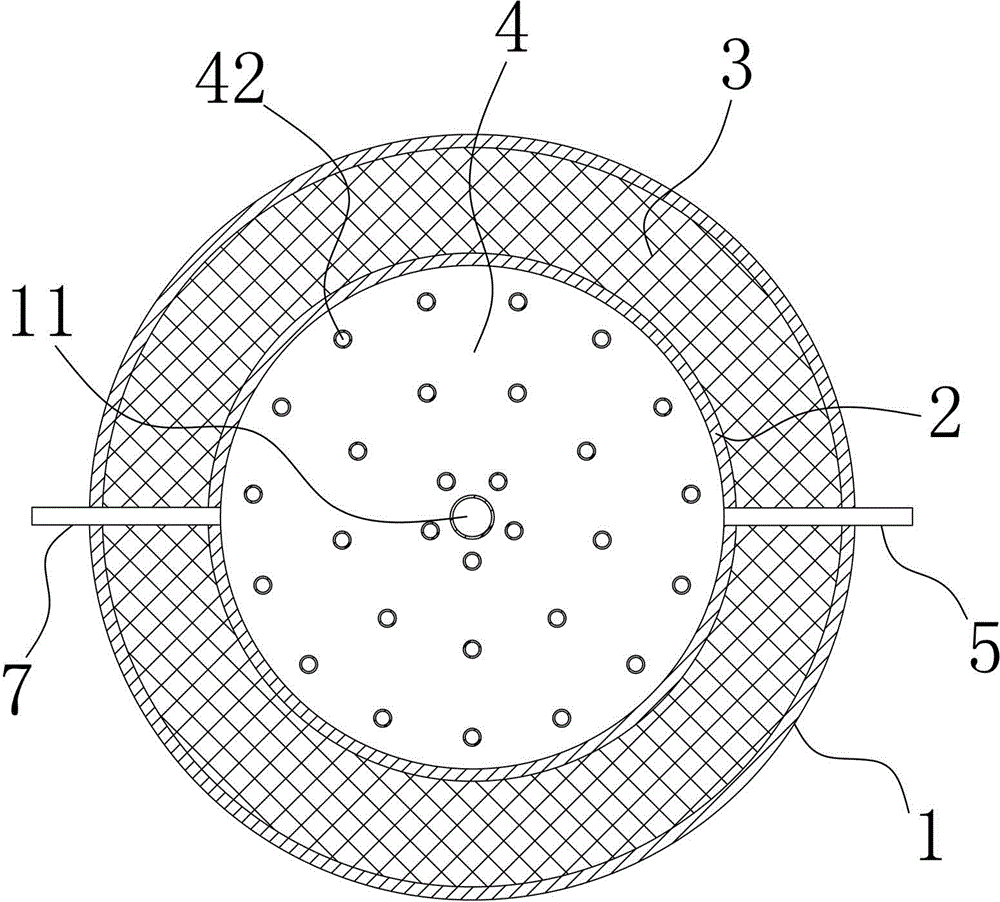
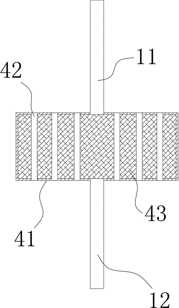
[0032] As attached figure 2 , 3 As shown, the energy storage body 4 includes an energy storage tank body 41 fixedly connected to the inner wall 2 of the water tank, a phase change material injection pipe 11, a phase change material dis...

Embodiment 2

[0037] See attached Figure 4 On the basis of embodiment 1, in this embodiment, the solar heat collection device is a hyperboloid solar heat collector 14 and a vacuum heat-conducting oil pipe 15 disposed thereon, and the water tank is also disposed in the water tank. The heat exchange coil 13, the two ends of the heat exchange coil 13 are connected to the solar water inlet 8 and the solar water return 7 respectively, and the two ends of the vacuum heat transfer oil pipe 15 are respectively connected to the solar water inlet 8 and the solar water return 7 . A two-dimensional sun tracking system 16 is also provided on the support of the solar thermal collector 14.

[0038] The solar collector adopts a hyperbolic parabolic arc reflecting mirror, which can greatly increase the amount of light. At the same time, a two-dimensional sun tracking control system is adopted to increase the heat collection efficiency of the solar collector to more than 90%. The heat is transferred through ...


PUM


Abstract

The invention relates to the technical field of an energy storage device and particularly relates to an energy storage device which is filled with phase change energy storage materials. The energy storage device comprises a water tank and an energy storage body arranged in the water tank, wherein the energy storage body comprises an energy storage box body which is fixedly connected with the inner wall of the water tank, a phase change material injection pipe, a phase change material leakage pipe, and a water passing pipe which is vertically arranged in the energy storage box body and is used for penetrating through the energy storage box body up and down; the energy storage box body is internally filled with phase change materials. The invention provides a heat accumulation device filled with the phase change materials; the phase change materials are used for storing solar energy and a water temperature is controlled in a certain range; not only are the requirements of heating water temperature met, but also the water supplying temperature is reduced; the heat radiation loss is reduced, the heat collection efficiency of a heat collector is improved and the heat accumulation amount is increased; the device is applied to combination use of a solar floor radiation heating system and the better effect can be obtained.

Description

Technical field [0001] The invention relates to the technical field of energy storage devices, in particular to an energy storage device equipped with phase change energy storage materials. Background technique [0002] my country is a populous country with 70% of the population living in rural areas. The energy consumption of vast rural areas has an important impact on my country's total energy supply and demand and its energy structure. Due to the architectural characteristics of rural residents, it is not suitable for centralized heating, so many residents still use earthen heating stoves for heating, coal cannot be used effectively, and carbon monoxide poisoning is prone to occur. With the improvement of the living standards of the masses of people in northern rural areas , People have a higher demand for winter heating equipment and methods. [0003] Solar low temperature floor heating system is a new building heating method that has been widely used in recent years. In the ...

Claims


Application Information

Patent Timeline
Patent Type & Authority Applications(China)
IPC IPC(8): F28D20/02F24J2/34
CPCY02E10/40Y02E60/14Y02E70/30
Inventor 李晓辉刘振法李海花宋宇涵牛庾鑫
Owner ENERGY RESOURCES INST HEBEI ACADEMY OF SCI
Why Eureka
Try Eureka