An x-shaped cross-polarized optical bridge based on a completely bandgap photonic crystal waveguide

A photonic crystal waveguide and cross-polarization technology, which is applied in the direction of light guides, optics, optical components, etc., can solve the problems of unfavorable large-scale optical path integration, design of polarization bridges, and insufficient volume, and achieve simple structure, easy cascading, and transmission high efficiency effect

Active Publication Date: 2017-08-25
SHENZHEN UNIV
View PDF5 Cites 0 Cited by
  • Summary
  • Abstract
  • Description
  • Claims
  • Application Information

AI Technical Summary

Problems solved by technology

However, the conventional polarization devices designed by these two methods cannot use their characteristics to design a polarization bridge, that is, a device that allows optical signals of different polarization states to cross-conduct at the waveguide node without interfering with each other.
In addition, although the above-mentioned photonic crystal waveguide is smaller than the traditional polarization device, its function is single, and the volume is still not small enough, which is not conducive to the integration of large-scale optical circuits.

Method used


Image

  • An x-shaped cross-polarized optical bridge based on a completely bandgap photonic crystal waveguide
  • An x-shaped cross-polarized optical bridge based on a completely bandgap photonic crystal waveguide
  • An x-shaped cross-polarized optical bridge based on a completely bandgap photonic crystal waveguide

Examples


Embodiment Construction

[0019] In order to make the object, technical solution and advantages of the present invention clearer, the present invention will be further described in detail below in conjunction with the accompanying drawings and embodiments. It should be understood that the specific embodiments described here are only used to explain the present invention, not to limit the present invention.

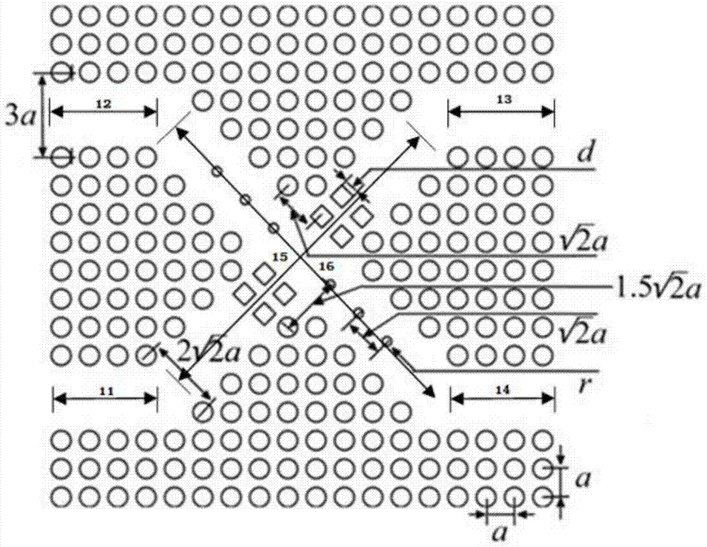
[0020] The embodiment of the present invention introduces such as figure 1 An X-shaped cross-polarized optical bridge based on a completely bandgap photonic crystal waveguide is shown, which specifically includes a TE input waveguide 11, a TM input waveguide 12, a TE output waveguide 13, a TM output waveguide 14, and a first connecting optical bridge 15 , the second connecting optical bridge 16 .

[0021] Among them, there is a first connecting optical bridge 15 between the TE input waveguide 11 and the TE output waveguide 13, and a square defect dielectric column is arranged in the first connecti...


PUM


Abstract

The invention is applicable to the field of mini optical polarized light bridges and provides an X-shaped cross polarized light bridge based on complete band gap type photonic crystal waveguides. The X-shaped cross polarized light bridge comprises a TE input waveguide, a TM input waveguide, a TE output waveguide and a TM output waveguide, wherein the TE input waveguide and the TM input waveguide are arranged parallelly along the first direction, a first connecting light bridge is arranged between the TE input waveguide and the TE output waveguide, and a square defective medium column is arranged in the first connecting light bridge. A second connecting light bridge is arranged between the TM input waveguide and the TM output waveguide, a circular defective medium column is arranged in the second connecting light bridge, the first connecting light bridge is perpendicularly intersected with the second connecting light bridge, and signals are outputted after passing the X-shaped cross polarized light bridge. The invention aims to provide the X-shaped cross polarized light bridge based on the complete band gap type photonic crystal waveguides, which is small in structural size, wide in operating length range, high in signal fidelity and electromagnetic wave transmission efficiency, applicable to massive light path integration and capable of realizing light path switching and shifting.

Description

technical field [0001] The invention belongs to the field of tiny optical polarization bridges, in particular to an X-shaped cross-polarization bridge based on a completely band-gap photonic crystal waveguide. Background technique [0002] Traditional optical bridges and polarized optical bridges mostly apply the principle of geometric optics, and their disadvantages are obvious: they are relatively large and cannot be used for optical path integration. On the basis of photonic crystals, devices that are small in size and easy to integrate with optical paths can be fabricated, including polarization bridges. Photonic crystal waveguides that build polarization bridges are generally constructed by introducing defects into photonic crystals with complete band gaps. From the perspective of polarization control and separation technology, there are generally two ways to achieve it: one is to use a photonic crystal with TE forbidden band and TM conduction band or TM forbidden band...

Claims


Application Information

Patent Timeline
Patent Type & Authority Patents(China)
IPC IPC(8): G02B6/126
CPCG02B6/1225G02B6/126
Inventor 林密欧阳征标金鑫文国华王晶晶
Owner SHENZHEN UNIV
Why Eureka
Try Eureka