Welding device, welding method, and method for producing cell

A welding device and welding method technology, applied in welding/welding/cutting items, manufacturing tools, welding equipment, etc., can solve the problem of inability to remove oxide film and the like

Inactive Publication Date: 2015-02-18
TOYOTA JIDOSHA KK
View PDF9 Cites 11 Cited by
  • Summary
  • Abstract
  • Description
  • Claims
  • Application Information

AI Technical Summary

Problems solved by technology

[0007] However, in the technique described in Patent Document 1, since laser light is irradiated on the surface of the molten pool, it is impossible to remove the oxide film remaining in the deep part of the molten pool.

Method used


Image

  • Welding device, welding method, and method for producing cell
  • Welding device, welding method, and method for producing cell
  • Welding device, welding method, and method for producing cell

Examples


no. 1 approach

[0049] Refer to the following Figure 1 to Figure 7 The welding apparatus 1 which is 1st Embodiment of the welding apparatus concerning this invention is demonstrated.

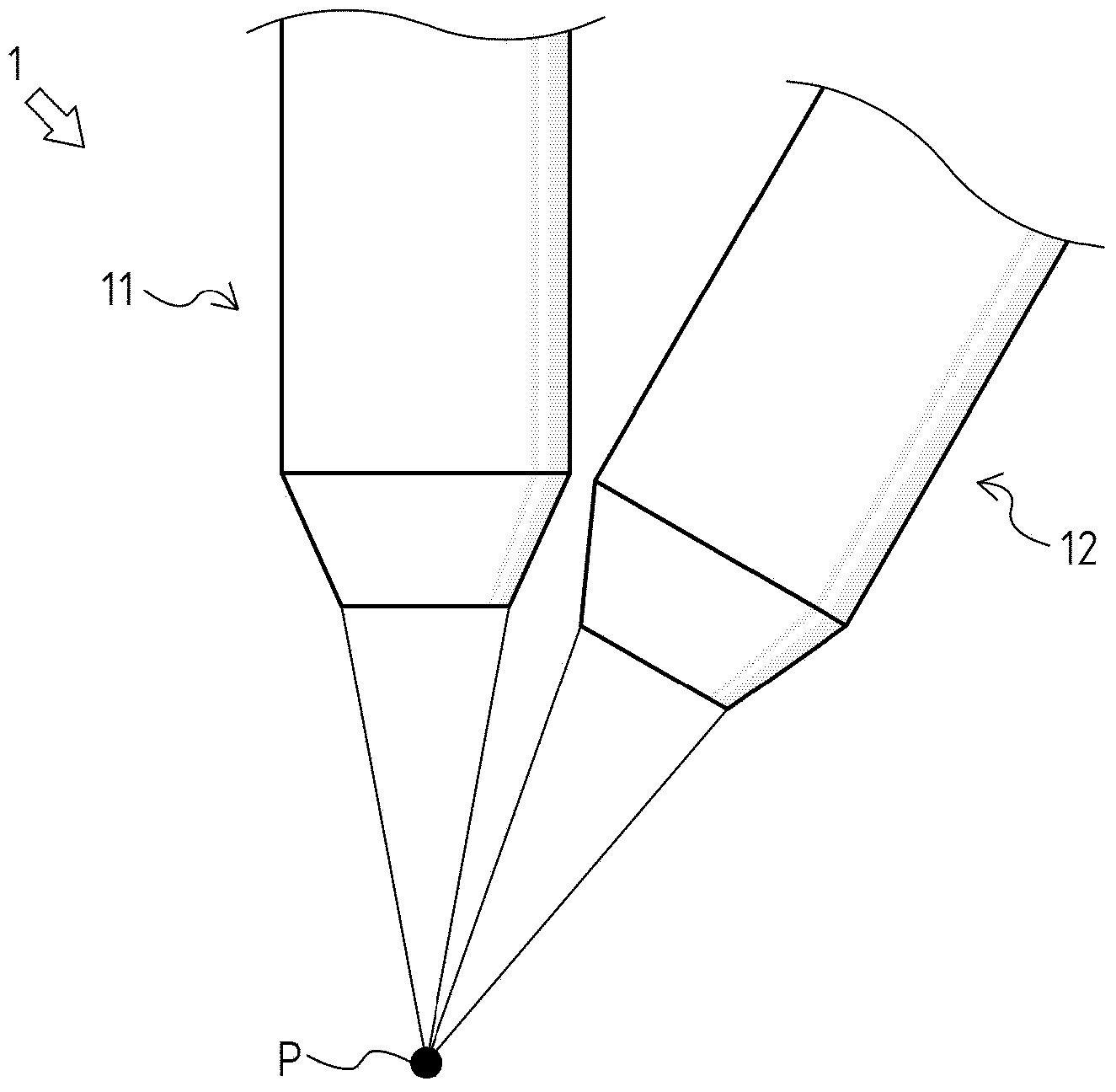
[0050] Such as figure 1 As shown, the welding device 1 includes a first welding torch 11 and a second welding torch 12 .

[0051] The first welding torch 11 and the second welding torch 12 irradiate predetermined laser beams respectively, and focus the laser beams on the processing point P. As shown in FIG.

[0052] In addition, below, the laser beam irradiated from the 1st welding torch 11 will be referred to as "1st laser beam", and the laser beam irradiated from the 2nd welding torch 12 will be referred to as "second laser beam".

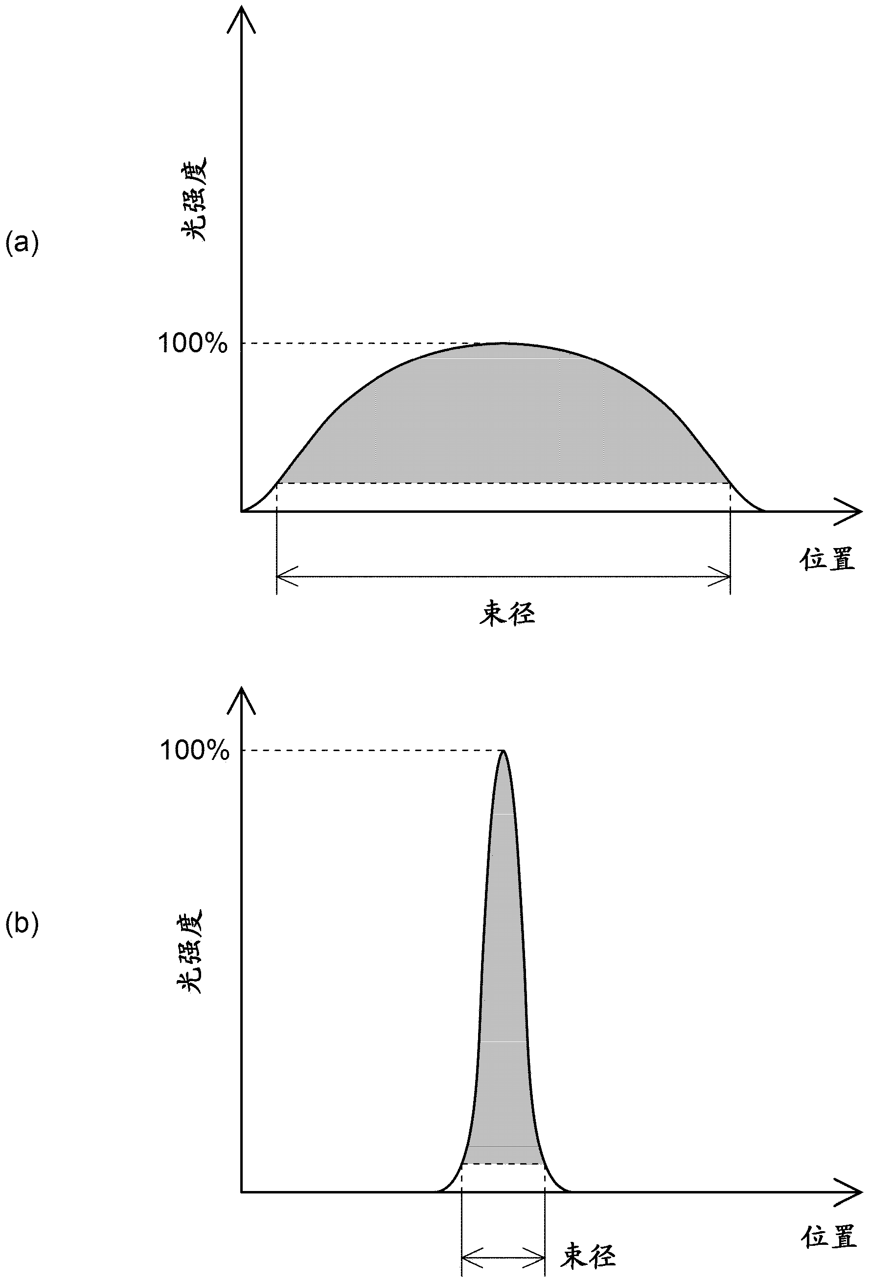
[0053] figure 2 (a) and figure 2 (b) shows the profile (light intensity distribution) of the 1st laser beam at the processing point P, and the profile (light intensity distribution) of the 2nd laser beam at the processing point P, respectively.

[0054] figure 2 (a) and ...

no. 2 approach

[0103] Refer to the following Figure 8 as well as Figure 9 The welding apparatus 2 which is 2nd Embodiment of the welding apparatus concerning this invention is demonstrated.

[0104] The welding device 2 includes a first welding torch 21 and a second welding torch 22 (not shown).

[0105]The first welding torch 21 and the second welding torch 22 have approximately the same configuration as the first welding torch 11 and the second welding torch 12 in the welding device 1 , respectively, and focus a predetermined laser beam on the processing point P. As shown in FIG.

[0106] In addition, below, the laser beam irradiated from the 1st welding torch 21 will be referred to as "1st laser beam", and the laser beam irradiated from the 2nd welding torch 22 will be referred to as "second laser beam".

[0107] Figure 8 (a) and Figure 8 (b) shows the profile (light intensity distribution) of the 1st laser beam at the processing point P, and the profile (light intensity distribut...


PUM

PropertyMeasurementUnit
melting pointaaaaaaaaaa

Abstract

Provided is a technique by which, in laser welding, the desired weld penetration depth can be achieved without any oxide film lingering in the deep part of a weld pool. Provided is a welding device (1) for emitting a laser focused on a processing point (P). At the processing point, the laser has a profile similar to that of a superimposed laser formed by superimposing a first laser and a second laser having a smaller beam radius than that of the first laser. In the laser profile, a portion corresponding to the first laser has a power density of an extent enabling heat conduction welding, and in the laser profile, a portion corresponding to the second laser has a power density of an extent enabling keyhole welding.

Description

technical field [0001] The present invention relates to techniques for suppressing welding defects in laser welding. Background technique [0002] Conventionally, laser welding in which base materials are joined to each other by melting the boundary portions of a plurality of base materials in contact with each other using a laser is widely known. [0003] In laser welding, when a metal (for example, aluminum) having a large difference between the melting point of the oxide film formed on the surface and the melting point of the inner part (non-oxidized part) of the oxide film is used as the base material, the oxide film itself It is difficult to directly melt with a laser, but since the non-oxidized part is easily melted, the oxide film is formed by the surface tension of the molten pool formed by the molten non-oxidized part and the convection generated in the molten pool due to the thermal gradient. destroyed. [0004] However, the above-mentioned convective force becom...

Claims


Application Information

Patent Timeline
Patent Type & Authority Applications(China)
IPC IPC(8): B23K26/26B23K26/21
CPCB23K26/3226B23K26/20B23K26/0613B23K2201/36B23K26/0617B23K26/243B23K26/0604B23K26/26B23K2203/10B23K2101/36B23K2103/10B23K26/32B23K26/242B23K2101/18B23K26/24B23K26/0608
Inventor 杉山彻中村秀生成濑洋一柴田义范
Owner TOYOTA JIDOSHA KK
Why Eureka
Try Eureka