

Aluminum electrolytic cell
An aluminum electrolytic cell and electrolyte technology, which is applied in the field of aluminum electrolytic cells, can solve problems such as increasing power consumption, and achieve the effects of reducing power consumption, reducing the probability of long anodes and reducing the cost of overhaul.
- Summary
- Abstract
- Description
- Claims
- Application Information
AI Technical Summary
Problems solved by technology
Method used
Image

Examples
Embodiment Construction
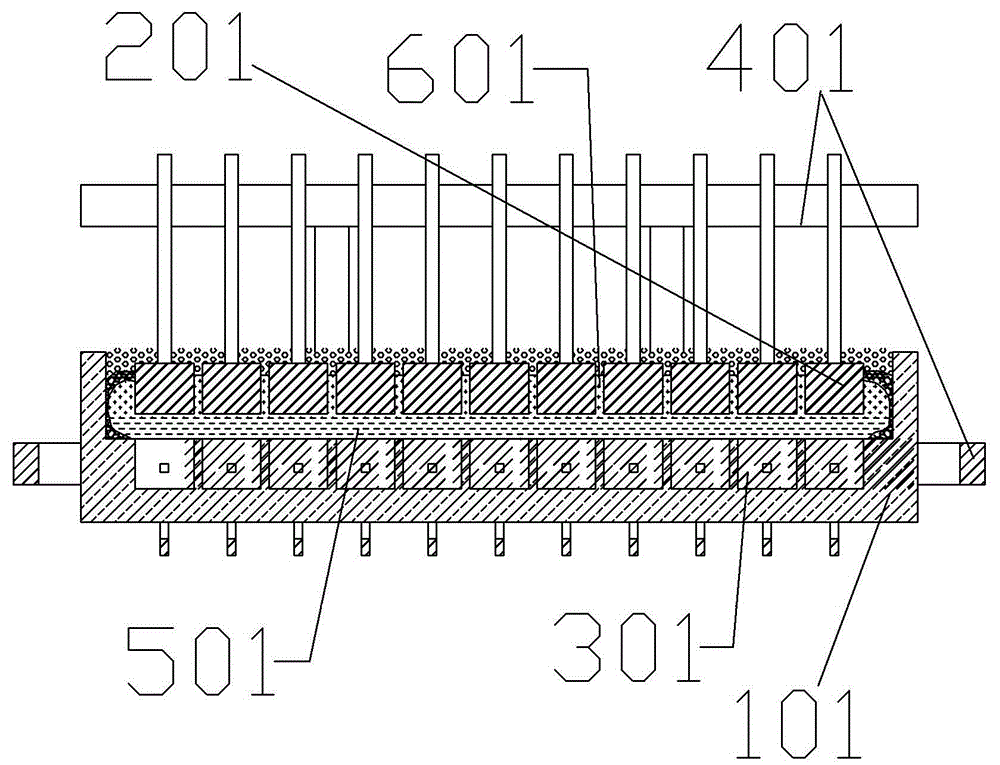
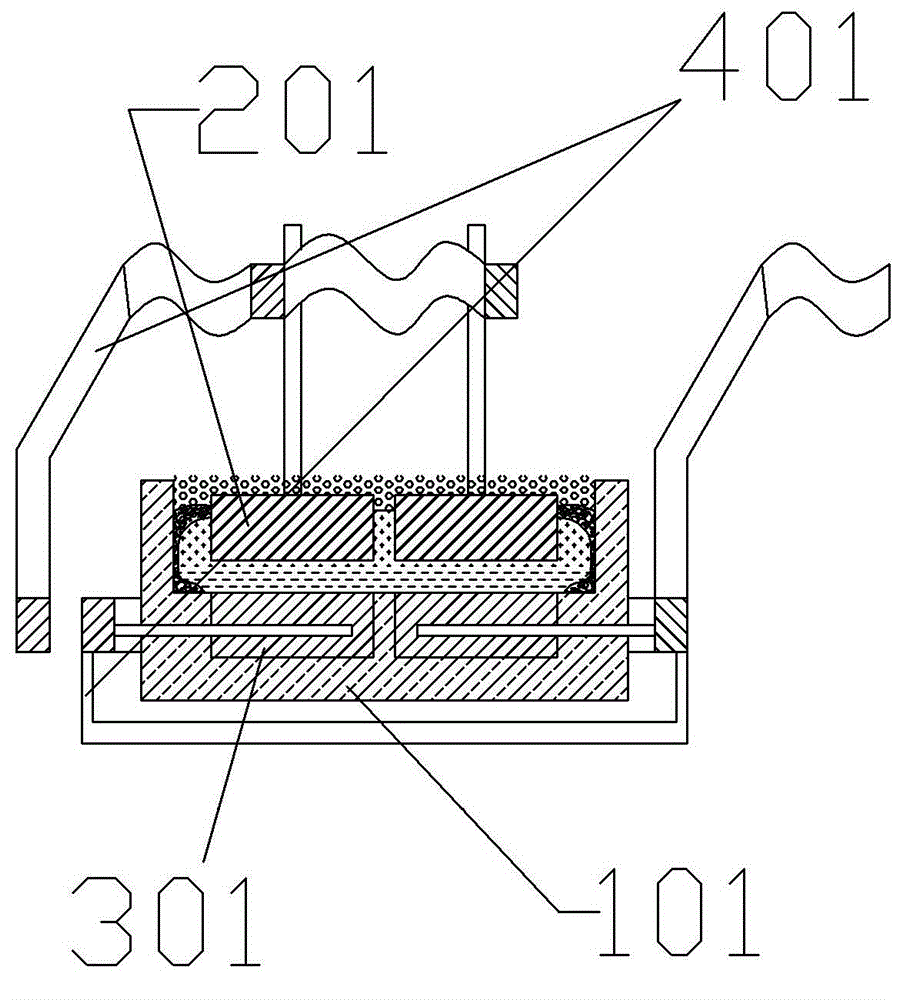
[0031] image 3 and Figure 4 It is a structural schematic diagram of a single-chamber electrolytic cell for aluminum electrolysis of the present invention, which are a front view and a left view respectively. Such as image 3 and Figure 4 As shown, the single-chamber electrolytic cell for aluminum electrolysis provided by the present invention is mainly composed of a cell body 1, a single cathode plate 2, and a single anode 8; the cell body 1 is a cavity structure, so The pole plate single anode 8 is located at the power inlet end in the tank body cavity, and the pole plate single cathode 2 is located at the power outlet end in the tank body cavity; the pole plate single cathode 2 is electrically connected with the negative pole 10 of the power supply, so The single anode 8 of the polar plate is electrically connected to the positive pole 9 of the power supply;
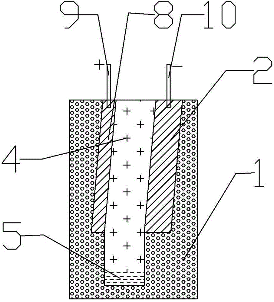
[0032] Such as Figure 5 and Figure 6 As shown, the aluminum electrolysis provided by the present inventio...
PUM
 Abstract
Description
Claims
Application Information