Automatic LCD screen detecting cabinet based on machine vision

A machine vision and LCD screen technology, applied in the direction of instruments, nonlinear optics, optics, etc., can solve the problems of false detection rate, high missed detection rate of detection equipment, assembly line detection in combination with production lines, and low detection efficiency, etc., to achieve Improved automation level, stable and reliable communication process, and improved efficiency

Active Publication Date: 2015-02-25
WUHAN JINGCE ELECTRONICS GRP CO LTD
View PDF7 Cites 45 Cited by
  • Summary
  • Abstract
  • Description
  • Claims
  • Application Information

AI Technical Summary

Problems solved by technology

[0002] At present, TFT LCD panel is the mainstream device in display equipment, and it is widely used in people's daily life. It is currently the only comprehensive performance such as brightness, contrast, power consumption, life, physical examination and weight that can catch up with and surpass CRT. Display devices, with the heating up of the liquid crystal display market, people are paying more and more attention to the liquid crystal display industry. In order to replace the traditional manual detection method, researchers began to introduce CCD (industrial camera) detection technology and design AOI (Automatic Optic Inspection) The system replaces human eye detection, but due to the interference of external natural light and dust impurities in the air on CCD detection and the interference of communication connections, the false detection rate and missed detection rate of detection equipment on the market are high, and the over-detection is serious, making it difficult to replace Human eye detection, at the same time, the integration level is not enough, and the detection efficiency is low (it is only a single experimental research equipment, which cannot be combined with the production line for pipeline detection)

Method used


Image

  • Automatic LCD screen detecting cabinet based on machine vision
  • Automatic LCD screen detecting cabinet based on machine vision
  • Automatic LCD screen detecting cabinet based on machine vision

Examples


Embodiment Construction

[0015] Below in conjunction with accompanying drawing and specific embodiment the present invention is described in further detail:

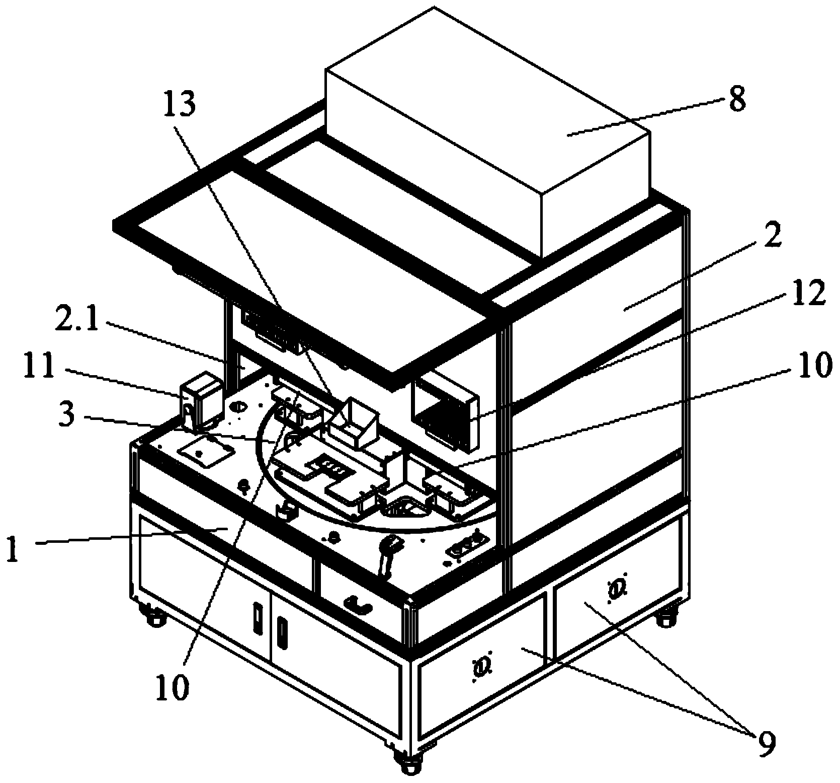
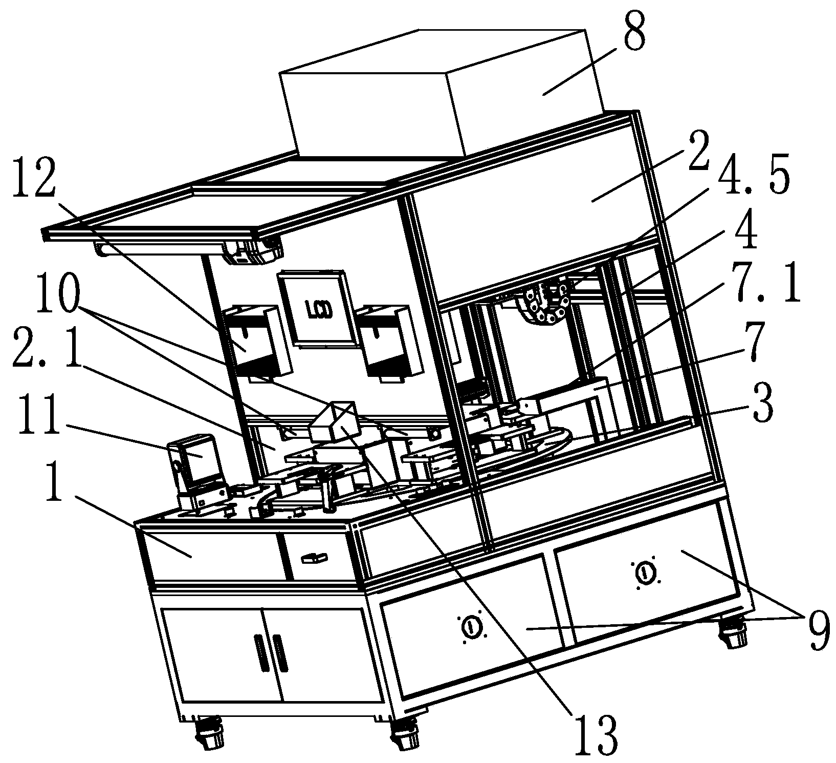
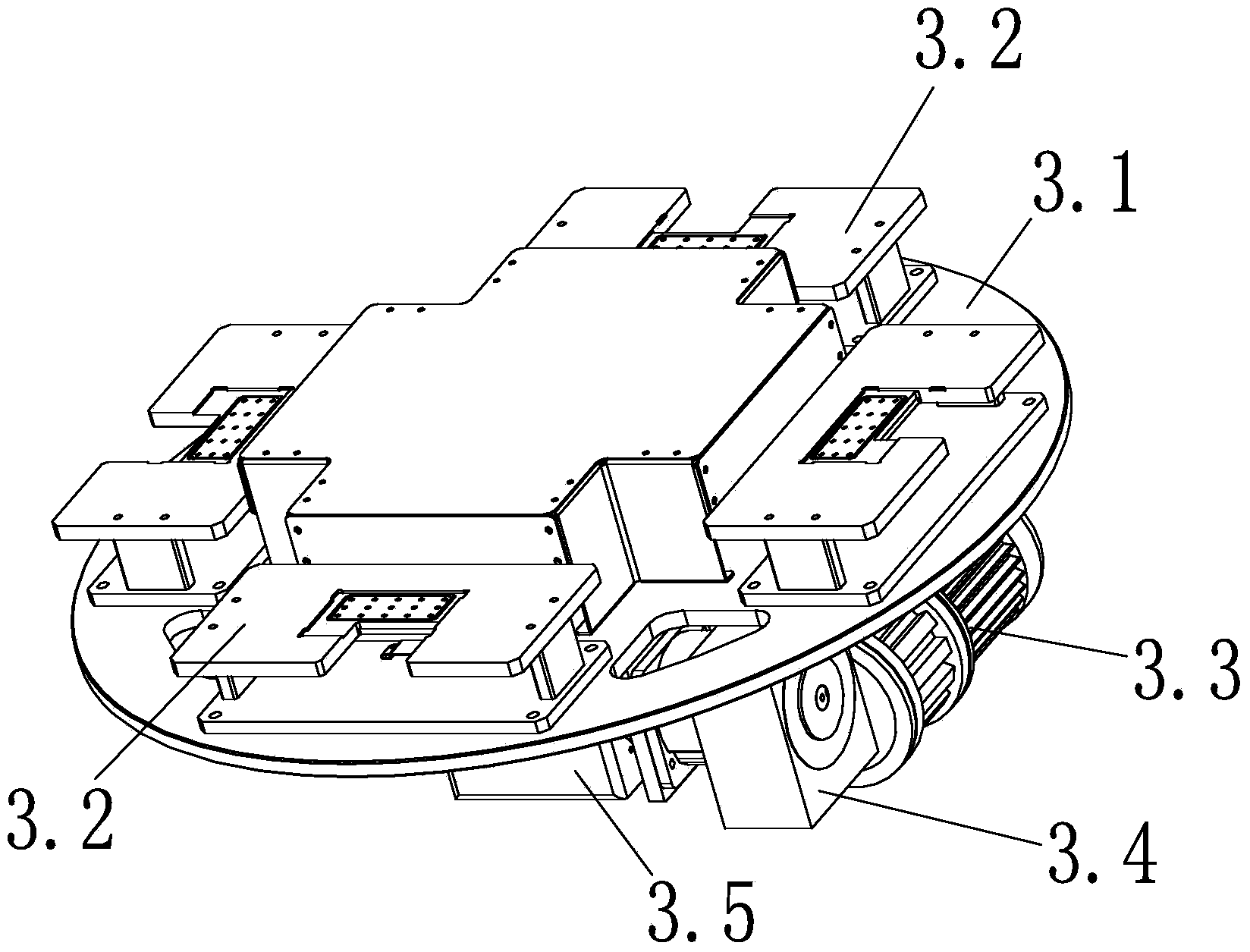
[0016] Such as Figure 1~6 The machine vision-based LCD screen automatic detection machine is shown, which includes a machine base 1, a dark room 2 composed of a front panel, a back panel, a top panel and two side panels, and a multi-station installed on the top of the machine base 1 Turntable system 3, PG automatic point screen system installed on the multi-station turntable system 3 and capable of sending test signals to the LCD screen 6 to be tested 5, installed on the top of the machine base 1 and capable of defect detection of the LCD screen 6 to be tested The machine vision automatic adjustment system 4, is arranged in the darkroom 2 and provides a light source 7.1 for detection illumination to the LCD screen 6 to be tested, wherein the top of the machine base 1 is fixedly connected to the bottom of the darkroom 2, and is located at the fr...


PUM


Abstract

The invention discloses an automatic LCD screen detecting cabinet based on machine vision. The automatic LCD screen detecting cabinet based on machine vision comprises a cabinet base, a darkroom, a multi-station rotating plate system, an automatic machine vision adjusting system and an automatic PG screen pointing system. The automatic PG screen pointing system comprises a graph signal generator, a pneumoelectric sliding ring, a power source, a computer and a plurality of signal rotating plates corresponding to LCD screen jigs in number. The automatic machine vision adjusting system comprises an industrial camera, a camera installation assembly, a perpendicular movement mechanical arm and a mechanical arm support. A light source support is further arranged on the top of the cabinet base, and a light source is arranged on the light source support and located between the industrial camera and the LCD screen jigs. The signal output end of the industrial camera is connected into the computer, and the control end of the perpendicular movement mechanical arm and the control end of the motor are connected into the computer. The automatic LCD screen detecting cabinet can eliminate the influences of external natural light and dust and impurities in the air on LCD screen defect detection, and meanwhile, the detecting cabinet has high integration degree, and the detecting efficiency of an LCD screen is greatly improved.

Description

technical field [0001] The invention relates to the technical field of automatic optical detection, in particular to a machine vision-based automatic detection machine for LCD screens. Background technique [0002] At present, TFT LCD panel is the mainstream device in display equipment, and it is widely used in people's daily life. It is currently the only comprehensive performance such as brightness, contrast, power consumption, life, physical examination and weight that can catch up with and surpass CRT. Display devices, with the heating up of the liquid crystal display market, people are paying more and more attention to the liquid crystal display industry. In order to replace the traditional manual detection method, researchers began to introduce CCD (industrial camera) detection technology and design AOI (Automatic Optic Inspection) The system replaces human eye detection, but due to the interference of external natural light and dust impurities in the air on CCD detect...

Claims


Application Information

Patent Timeline
Patent Type & Authority Applications(China)
IPC IPC(8): G02F1/13
CPCG02F1/1309
Inventor 彭骞侯浪张佳张力陈凯沈亚非
Owner WUHAN JINGCE ELECTRONICS GRP CO LTD
Why Eureka
Try Eureka